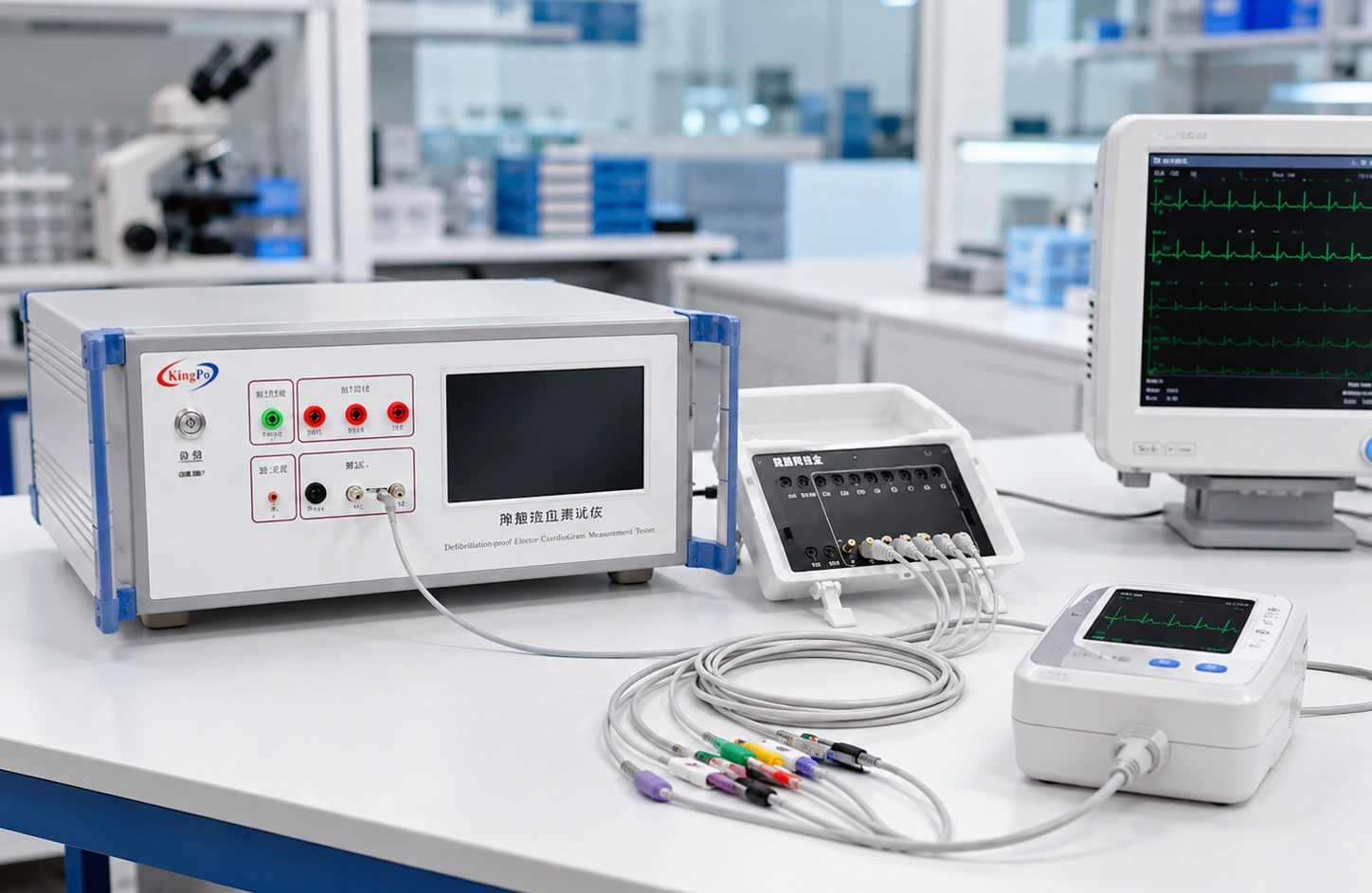
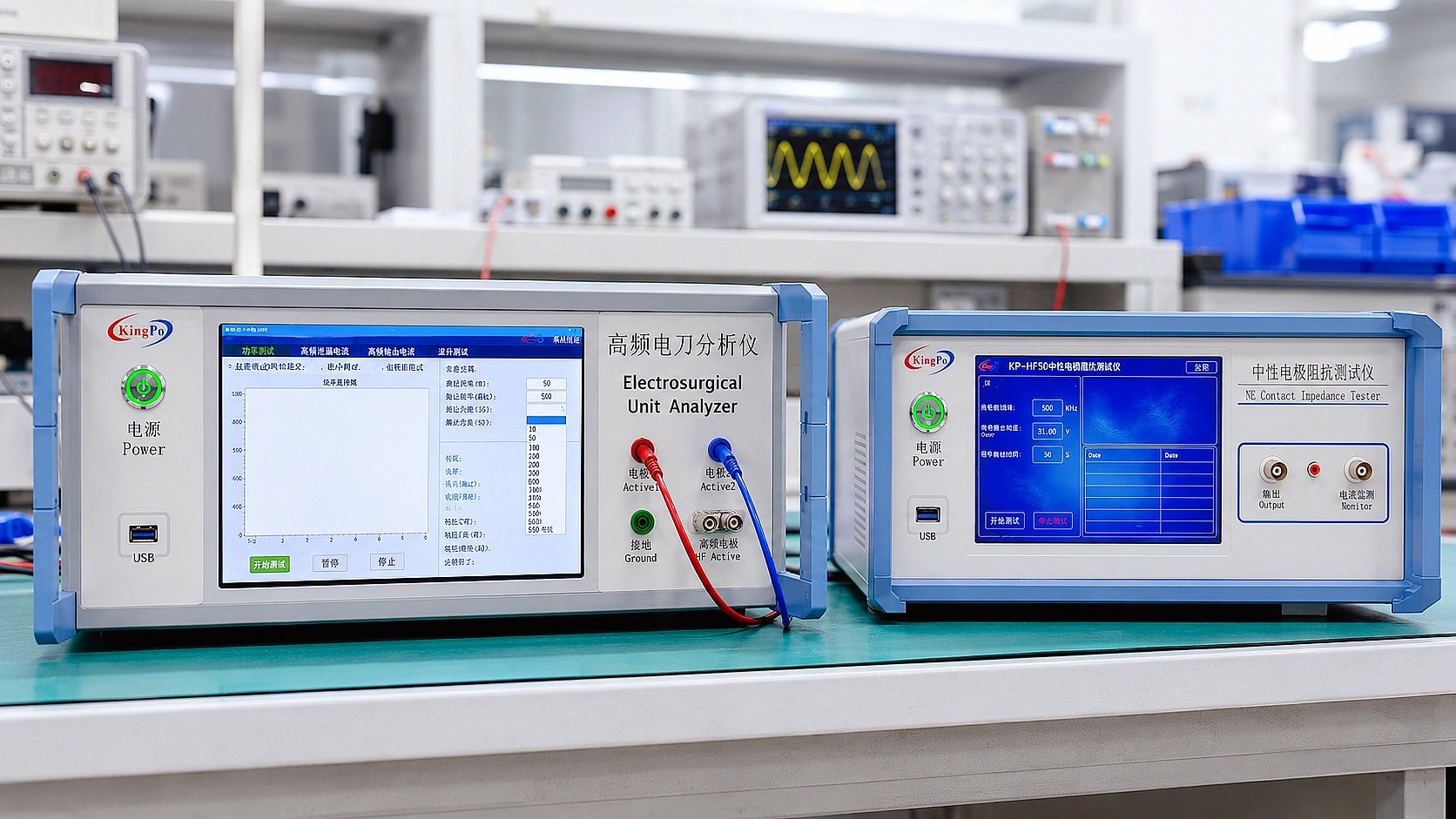
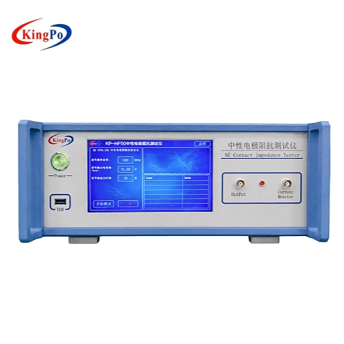
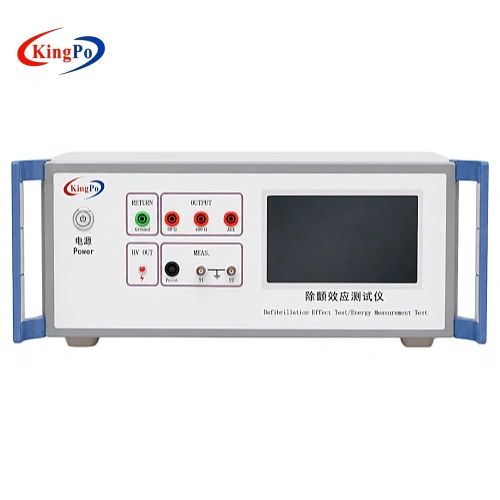
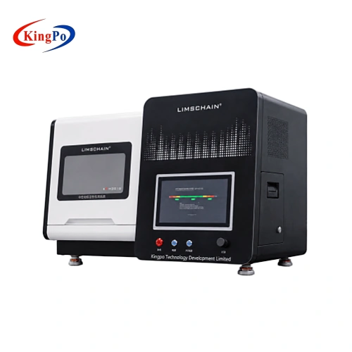
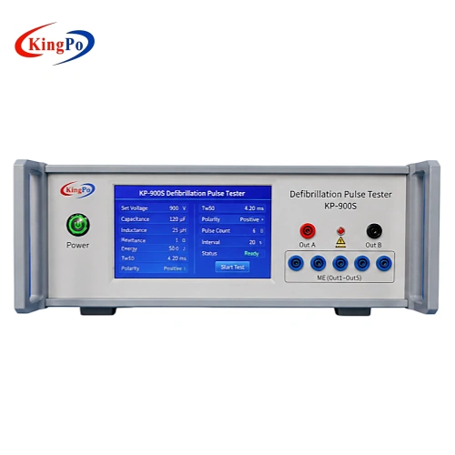
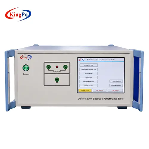
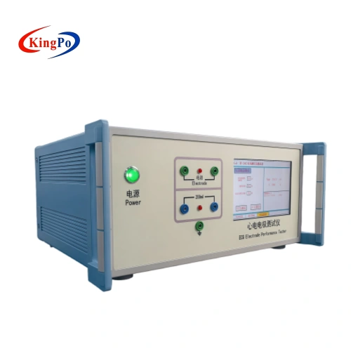
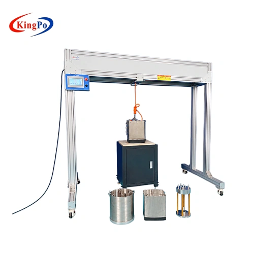
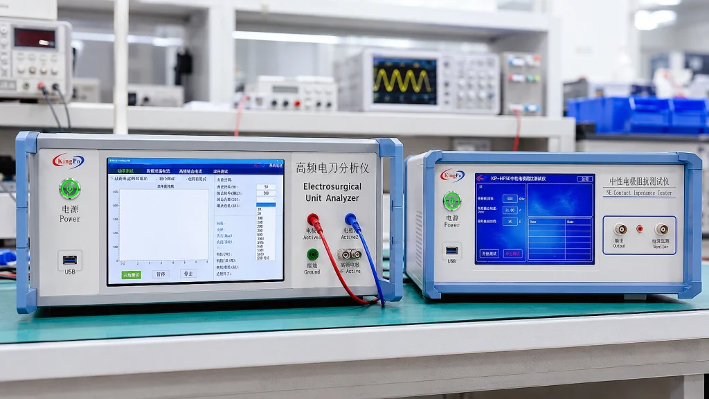
IEC 60601-2-2, which specifies particular requirements for the basic safety and essential performance of high-frequency surgical equipment and accessories, is supported by test systems manufactured by KingPo Technology Development Limited, including the KP8850 ESU Analyzer, KP-HF50 Neutral Electrode Contact Impedance Tester and ZLR-320 Neutral Electrode Temperature Rise Tester for generator output, REM/CQM, HF electrode impedance and thermal-performance evaluation.
IEC 60601-2-2 testing rarely becomes difficult because a laboratory cannot identify the standard. The harder part is determining whether the measurement system actually represents the electrosurgical generator, accessory and neutral-electrode configuration being evaluated.
A typical request may contain only a few words:
“IEC 60601-2-2, 300 W ESU — please quote the test equipment.”
That is not yet enough to define the test bench. Before selecting an ESU analyzer, HF load, voltage probe, leakage-current arrangement or neutral-electrode tester, engineers need to understand the generator’s maximum voltage, operating frequency, CUT and COAG waveforms, monopolar and bipolar modes, power-versus-load behaviour, REM/CQM architecture and the specific neutral-electrode test requirement.
This article reviews seven practical issues worth resolving before the test begins, with particular attention to the measurement chain and the differences between generator testing, neutral-electrode electrical testing and neutral-electrode thermal testing.
Technical Overview
- Primary standard: IEC 60601-2-2 for high-frequency surgical equipment and accessories
- Generator measurements: Output power, load curve, HF voltage/current, HF leakage and REM/CQM
- Neutral-electrode electrical test: Contact impedance / capacitance — KP-HF50
- Neutral-electrode thermal test: Temperature rise — ZLR-320
- Key engineering principle: Select equipment from the test quantity, DUT and circuit—not from rated wattage or voltage alone
Where IEC 60601-2-2 ISH1:2025 Fits
IEC 60601-2-2:2017 addresses the basic safety and essential performance of high-frequency surgical equipment and high-frequency surgical accessories. Amendment 1 followed in 2023, and Interpretation Sheet 1 was published in 2025.
ISH1:2025 is particularly relevant to the EMC configuration of HF surgical equipment and accessories. For EMC evaluation, operating mode, accessories, cable lengths and physical arrangement can materially affect the test configuration and therefore need to be documented and reproduced appropriately.
That interpretation should not be confused with a new electrical output test. An IEC 60601-2-2 laboratory may still require separate work on output power, load curves, HF voltage/current, HF leakage, REM/CQM and neutral-electrode performance.
1. Rated Power Alone Does Not Define the ESU Test Bench
A 300 W rating is useful information, but it does not describe the complete electrical envelope of an electrosurgical generator.
Two generators with the same rated output power may operate at different load resistances, use different control strategies and produce very different peak voltage or pulse-modulated COAG waveforms.
Before selecting equipment, laboratories should normally confirm:
| Information | What to Check | Why It Matters |
|---|---|---|
| Rated power | Load resistance at which the rating applies | Generator output changes with load resistance |
| Maximum voltage | Maximum Vpp for each relevant operating mode | Determines voltage-measurement and probe requirements |
| Operating frequency | Fundamental and relevant HF range | Loads, probes, sensors and cables become frequency-dependent |
| Operating mode | CUT, COAG, BLEND, monopolar and bipolar modes | Continuous and pulse-modulated waveforms produce different measurement conditions |
| Neutral-electrode system | REM/CQM architecture and electrode construction | Generator monitoring and electrode characterization are separate tests |
A Load Curve Usually Tells More Than One Power Reading
For an ideal resistive load:
P = VRMS2 / R
or
P = IRMS2 × R
An ESU is an actively controlled source. Changing the load can change the generator’s operating point, so a measurement at one resistance only describes what happened at that resistance.
A load-power curve provides a more useful picture of generator behaviour across the required operating range.
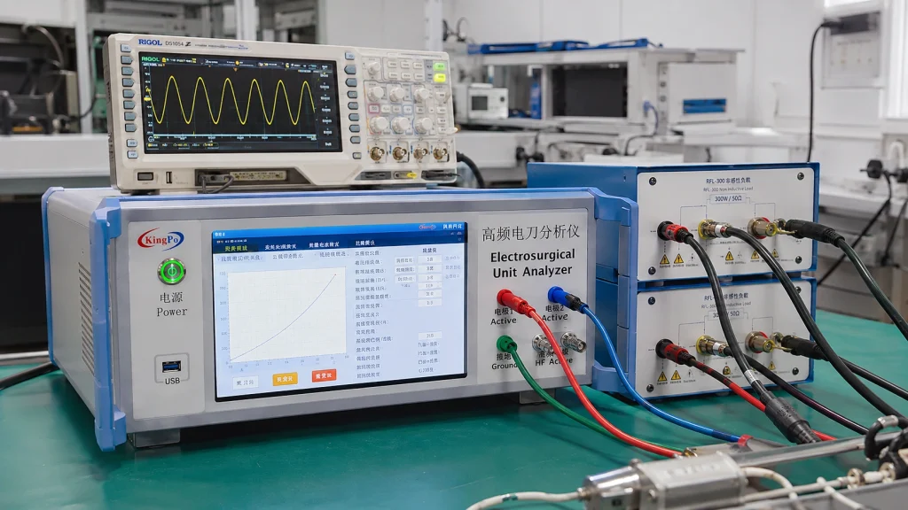
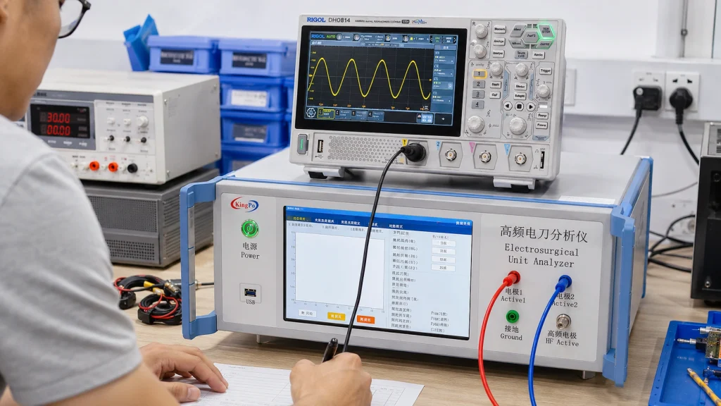
The KP8850 ESU Analyzer supports internal load settings from 0–2000 Ω and automatic impedance switching for multi-point load-power curve testing.
| KP8850 Measurement | Range / Capability |
|---|---|
| Output power | 0–500 W, 0.1 W resolution |
| Load resistance | 0–2000 Ω |
| HF voltage | 0–5 kV peak-to-peak |
| HF current | 2–5000 mA RMS |
| HF leakage current | 20–1000 mA |
| REM / CQM simulation | 0–2000 Ω |
2. A 5 kV Probe Is Not Defined by Voltage Rating Alone
If an ESU can generate approximately 5 kV peak-to-peak and a laboratory owns a probe labelled “5 kV,” those two numbers alone do not establish measurement suitability.
Before using the probe for an electrosurgical waveform, review:
- whether the voltage rating is DC, RMS, peak or peak-to-peak;
- allowable voltage versus frequency;
- probe bandwidth;
- input capacitance;
- common-mode limitations;
- grounding arrangement;
- attenuation accuracy;
- calibration coverage at the actual test frequency and amplitude.
This becomes particularly important for COAG, spray and other pulse-modulated waveforms. Similar average power does not mean similar peak voltage, duty cycle or crest factor.
The KP8850 measures HF voltage up to 5 kV peak-to-peak and HF current up to 5000 mA RMS. Where detailed oscilloscope waveform analysis is needed, the laboratory’s existing oscilloscope and probe should be evaluated first rather than automatically replacing them.
3. At High Frequency, the Load Is More Than Its Resistance Value
A resistor labelled 500 Ω may be nominally 500 Ω, but the complete HF test loop is not purely resistive.
The resistor body, terminals, leads, cables and fixture geometry add inductance, capacitance and coupling. At higher frequencies, the complete arrangement is better considered as a frequency-dependent impedance:
Z = Z(f)
This deserves particular attention with physically large, high-power load networks and testing that extends into the megahertz range.
Cable length, conductor spacing, shielding, grounding and the distance between the ESU, load and measuring instrument can all influence the same electrical loop.
For repeatable testing, laboratories should document:
- load construction;
- nominal resistance;
- test frequency;
- connection method;
- cable type and length;
- fixture geometry;
- grounding arrangement.
At several megahertz, the fixture can become part of the measurement system rather than merely a mechanical support.
For a deeper discussion, see our 4 MHz Electrosurgical Output Power Test Analysis.
4. HF Leakage, EMC and IEC 60601-1 Leakage Are Different Tests
The terminology is similar enough to create confusion, but these measurements answer different questions and require different equipment.
| Measurement | Engineering Question | Typical Measurement System |
|---|---|---|
| EMC emissions / immunity | What electromagnetic disturbance is produced or tolerated by the equipment? | Applicable EMC receiver, antennas, LISN or coupling networks and defined EMC environment |
| HF leakage current | Where is unintended high-frequency surgical current flowing? | HF-capable ESU analyzer and the applicable IEC 60601-2-2 arrangement |
| IEC 60601-1 leakage current | What general medical electrical leakage current exists under the specified conditions? | Medical electrical safety analyzer and applicable measuring network |
The KP8850 provides a dedicated HF leakage-current measurement range of 20–1000 mA for electrosurgical applications.
That function does not replace an IEC 60601-1-2 EMC system, and an EMC receiver does not replace an ESU analyzer.
A useful procurement rule is:
Start with the electrical quantity and the required test network—not with the fact that several requirements contain the words “high frequency.”
5. REM/CQM, Contact Impedance and Temperature Rise Are Three Different Neutral-Electrode Questions
This is one of the most important distinctions to settle before selecting IEC 60601-2-2 equipment.
All three tests involve the neutral electrode, but the actual engineering question is different.
| Test | What Is Being Evaluated? | KingPo Equipment |
|---|---|---|
| REM / CQM | Whether the electrosurgical generator correctly detects changes in the return-electrode monitoring circuit and responds at the required threshold | KP8850 ESU Analyzer |
| Neutral-electrode contact impedance / capacitance | The high-frequency electrical characteristics of the neutral-electrode connection itself | KP-HF50 Neutral Electrode Contact Impedance Tester |
| Neutral-electrode temperature rise | The thermal performance and local temperature distribution of the neutral electrode under HF current | ZLR-320 Neutral Electrode Temperature Rise Tester |
A generator may correctly detect changes in simulated REM/CQM resistance while the neutral electrode still requires independent HF electrical and thermal evaluation.
Similarly, a good contact-impedance result does not demonstrate acceptable temperature rise, and an acceptable temperature-rise result does not verify generator alarm logic.
The three product roles should therefore remain separate:
- KP8850: generator-side REM/CQM simulation and response;
- KP-HF50: electrode-side HF contact impedance or capacitance;
- ZLR-320: electrode thermal performance and temperature rise.
6. A DC Ohmmeter Cannot Replace the HF Neutral-Electrode Test
A DC resistance measurement is useful for continuity checks and troubleshooting, but it does not reproduce the electrical behaviour of a neutral electrode at electrosurgical frequencies.
At hundreds of kilohertz and several megahertz, resistance, capacitance and parasitic effects all contribute to the measured result.
For a conductive neutral-electrode connection, HF contact impedance can be determined from RMS voltage and current:
Zc = Utest / Itest
Capacitive neutral electrodes require a different calculation because frequency is part of their electrical behaviour. A single DC resistance value therefore cannot represent both conductive and capacitive electrode constructions.
The KP-HF50 Neutral Electrode Contact Impedance Tester is designed for the contact-impedance test method associated with IEC 60601-2-2 Clause 201.15.101.6.
| KP-HF50 Parameter | Specification |
|---|---|
| Test signal | High-frequency sine wave |
| Principal test frequencies | 200 kHz, 500 kHz, 1 MHz, 2 MHz and 5 MHz |
| Frequency accuracy | ≤ ±0.1% |
| Maximum test current | >200 mA RMS at ≤50 Ω load |
| Maximum output voltage | 12 Vrms, approximately 36 Vpp |
| Current measurement frequency range | 50 kHz–5 MHz |
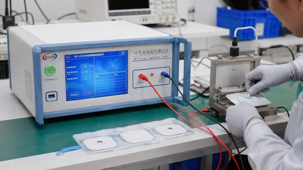
The multiple test frequencies are important because the electrical behaviour of the electrode should not be assumed to remain constant over the complete electrosurgical frequency range.
7. Calibration and Test Configuration Must Be Defined Before Testing Starts
A measurement chain can be electrically suitable and still create problems later if its calibration coverage does not include the actual working points used during the test.
For IEC 60601-2-2 work, the statement “the instrument is calibrated” is not enough. Laboratories should determine:
- which quantities are calibrated;
- the calibrated voltage and current ranges;
- the calibrated power range;
- the relevant HF frequencies;
- the load or resistance values;
- probe and sensor calibration coverage;
- the certificate and traceability requirements for the project.
If testing will be performed at 500 kHz, 1 MHz and 5 MHz, for example, calibration evidence should be reviewed against the actual measurement functions and frequency points used by the laboratory.
ISH1:2025 Reinforces the Importance of Configuration
The same principle applies to EMC configuration. For HF surgical equipment, operating mode, accessory selection, cable length and physical arrangement can form part of the test evidence.
A reproducible laboratory setup should therefore document enough information for another engineer to understand how the test was actually performed.
The broader lesson is simple: at high frequency, configuration is part of the measurement.
Build the Measurement Chain Around the Test Question
An IEC 60601-2-2 laboratory is normally a combination of measurement functions rather than one universal instrument.
| Test Function | Typical Equipment | What Drives the Configuration? |
|---|---|---|
| Output power / load curve | KP8850 ESU Analyzer | Rated power, load range, generator mode and waveform |
| HF voltage / current / waveform | KP8850 plus suitable HF probes or oscilloscope where required | Maximum Vpp, RMS current, bandwidth, crest factor and waveform type |
| HF leakage current | KP8850 ESU Analyzer | Applicable leakage path, mode and HF test network |
| REM / CQM generator monitoring | KP8850 ESU Analyzer | Generator monitoring architecture, resistance threshold and alarm behaviour |
| Neutral-electrode contact impedance / capacitance | KP-HF50 | Electrode type, cable configuration and required HF test frequencies |
| Neutral-electrode temperature rise | ZLR-320 | Electrode thermal-performance method, test current and temperature distribution |
| IEC 60601-1 general leakage | Medical electrical safety analyzer | Applicable measuring network and normal/single-fault conditions |
| EMC | Applicable EMC test system | Operating state, accessories, cables, layout and relevant EMC configuration |
Information to Confirm Before Requesting an IEC 60601-2-2 Test System
A useful equipment recommendation normally starts with the following information:
- ESU model and rated power: Include CUT, COAG, BLEND, monopolar and bipolar modes where relevant.
- Maximum HF voltage and operating frequency: Especially the highest Vpp and frequency by mode.
- Required tests: Output power, load curve, HF leakage, REM/CQM, neutral-electrode contact impedance or temperature rise.
- Neutral-electrode configuration: Conductive or capacitive design, cable arrangement and monitoring architecture.
- Existing laboratory instruments: Oscilloscope, HV probe, current sensor, loads and general IEC 60601 safety analyzer.
- Calibration and reporting requirements: Frequency points, measurement ranges, certificate requirements and required test records.
Frequently Asked Questions
Can one instrument perform every IEC 60601-2-2 test?
No. IEC 60601-2-2 work can involve generator output measurement, HF leakage, REM/CQM, neutral-electrode electrical characterization, neutral-electrode thermal performance and EMC. These are different measurement functions and may require different instruments or test systems.
What is the difference between REM/CQM and neutral-electrode contact impedance testing?
REM/CQM evaluates whether the electrosurgical generator correctly monitors changes in the return-electrode circuit. Contact-impedance testing evaluates the high-frequency electrical characteristics of the neutral-electrode connection itself. The KP8850 supports generator-side REM/CQM simulation, while KP-HF50 is dedicated to electrode-side HF contact impedance or capacitance testing.
What is the difference between KP-HF50 and ZLR-320?
KP-HF50 measures the high-frequency electrical contact impedance or capacitance of a neutral electrode and is associated with IEC 60601-2-2 Clause 201.15.101.6. ZLR-320 evaluates neutral-electrode thermal performance and temperature rise and is associated with Clause 201.15.101.5.
Can a DC resistance meter be used instead of KP-HF50?
No. A DC resistance meter does not reproduce the frequency-dependent electrical behaviour of a neutral electrode at hundreds of kilohertz or several megahertz. Dedicated HF voltage/current measurement is required for the contact-impedance or capacitance evaluation.
Does a 5 kV probe automatically work for a 5 kVpp ESU waveform?
Not necessarily. The laboratory should also review the probe’s voltage-rating definition, allowable voltage versus frequency, bandwidth, input capacitance, grounding method, attenuation accuracy and calibration coverage.
Why is the load curve important for an ESU?
An electrosurgical generator is an actively controlled source, so output power can change with load resistance. A multi-point load-power curve provides a more complete view of generator behaviour than one power measurement at a single resistance.
Which KingPo equipment is used for neutral-electrode temperature-rise testing?
The ZLR-320 Neutral Electrode Temperature Rise Tester is intended for thermal-performance evaluation of neutral electrodes under controlled high-frequency current conditions.
Conclusion
The most common IEC 60601-2-2 equipment-selection errors occur when laboratories begin with one headline parameter—300 W, 5 kV or a standard number—rather than the actual test question.
A reliable configuration begins by identifying:
DUT → test function → operating mode → electrical quantity → test network → frequency range → calibration requirement.
For electrosurgical-generator output, load-curve, HF leakage and REM/CQM testing, see the KP8850 ESU Analyzer.
For neutral-electrode HF contact impedance or capacitance testing, see the KP-HF50 Neutral Electrode Contact Impedance Tester.
For neutral-electrode thermal performance and temperature-rise testing, see the ZLR-320 Neutral Electrode Temperature Rise Tester.