Electric strength testing, also known as dielectric strength testing or hipot testing, is an important insulation verification method under IEC 62368-1. It evaluates whether electrical insulation can withstand a specified high voltage without breakdown, helping verify the effectiveness of insulation barriers used to protect against electric shock.
The test applies to insulation structures in audio/video equipment, information technology equipment and communication technology products. It is particularly relevant when evaluating basic insulation, supplementary insulation and reinforced insulation between different conductive parts.
However, a reliable electric strength test involves more than applying high voltage and checking for an alarm. Specimen preparation, temperature and humidity conditioning, electrode placement, test voltage selection and breakdown evaluation all need to follow the applicable requirements. This article explains the key procedures under IEC 62368-1:2023, Clauses 5.4.1.4, 5.4.8 and 5.4.9. For a broader overview of the standard’s testing requirements and laboratory equipment, see the IEC 62368-1 test equipment guide.
Electric Strength Test at a Glance
| Standard | IEC 62368-1:2023 |
| Relevant Clauses | 5.4.1.4, 5.4.8 and 5.4.9 |
| Test Method | AC or DC high-voltage testing |
| Type Test Duration | 60 seconds at the prescribed voltage |
| Routine Test Duration | 1–4 seconds |
| Acceptance Criterion | No insulation breakdown |
1. Purpose and Principle of Electric Strength Testing
An electric strength test evaluates the ability of an insulation system to withstand a specified electrical stress. During testing, a voltage difference is applied between two conductive parts separated by insulation.
If the insulation is insufficient or has been weakened by thermal, environmental or manufacturing factors, the applied voltage may cause dielectric breakdown. This can result in an uncontrolled increase in current or an electrical discharge through the insulating material.
Typical test applications include:
- Insulation between mains input circuits and accessible conductive parts.
- Insulation between primary and secondary circuits in power supplies.
- Basic, supplementary and reinforced insulation systems.
- Insulating barriers in electronic assemblies and AV/ICT equipment.
- Solid insulation and applicable thin-sheet insulating materials.
Electric strength testing and insulation resistance testing serve different purposes. Insulation resistance testing measures the resistance of an insulating path under a specified voltage, while electric strength testing verifies whether the insulation can withstand the prescribed high-voltage stress without breakdown. One test cannot replace the other.
2. Test Equipment and Specimen Preparation
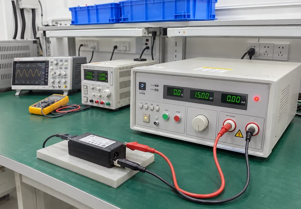
A typical test setup uses an AC/DC high-voltage tester, test electrodes, connection leads and suitable specimen fixtures. Depending on the insulation structure, conductive metal foil and additional measuring or protective accessories may also be required.
Before testing, verify the tester’s operating condition, calibration status, output connections and protective functions. The high-voltage leads and electrodes should be inspected for damage, and the specimen should be positioned securely.
Electrode Connection
The connection arrangement depends on the insulation barrier being evaluated. Identify the conductive parts on both sides of the insulation and connect the high-voltage and return electrodes accordingly.
- Complete equipment: Relevant conductive terminals or circuit groups on each side of the insulation barrier may be connected together according to the test arrangement. The connections must correspond to the specific insulation path under evaluation.
- Insulating enclosures: Where required, conductive metal foil can be placed against the insulating surface to form a test electrode. The foil should cover the relevant area without creating unintended discharge paths.
- Thin-sheet insulation: Use suitable electrodes and fixtures to hold the material in the specified test position. The specimen must be large enough to avoid edge-related breakdown affecting the result.
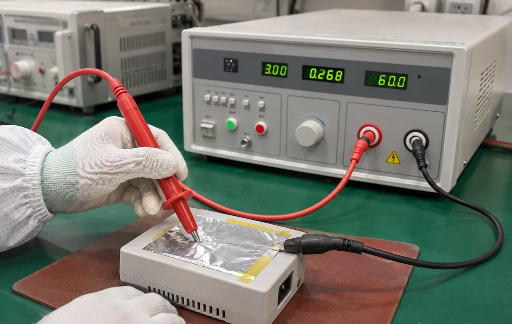
Metal foil is particularly useful when evaluating insulation near sharp metal edges or other locations where the insulation may be electrically weak. According to Clause 5.4.9.1, foil placement should be controlled to prevent flashover around the specimen edges. Where adhesive metal foil is used, the adhesive must be conductive.
Practical point
Metal foil dimensions should not be treated as a universal fixed value. The required size and position depend on the specimen geometry, insulation structure and applicable test arrangement.
3. Temperature and Humidity Conditioning
Insulation performance can change when materials are exposed to elevated temperatures or high humidity. For this reason, specimen conditioning is an important part of the electric strength test sequence.
Temperature Test – Clause 5.4.1.4
Clause 5.4.1.4 specifies the maximum operating temperatures for insulating materials, components and electrical insulation systems (EIS) under normal operating conditions.
The temperature limits depend on the insulation material or declared thermal class of the EIS. For example, the standard specifies a maximum temperature of 100°C for Class 105 (A) insulation and higher limits for higher thermal classes.
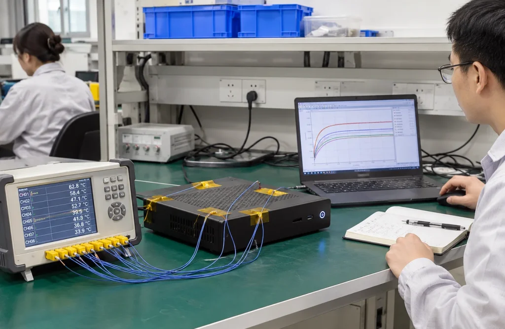
During the temperature test, equipment is operated under its normal operating conditions according to its operating mode:
- Continuous operation: Operate until steady-state conditions are established.
- Intermittent operation: Use the rated ON/OFF periods until steady-state conditions are established.
- Short-time operation: Operate for the time specified by the manufacturer.
Installation conditions must also be considered. For equipment intended for flush-mounted installation, rack mounting or assembly inside larger equipment, the temperature test should reflect the least favourable actual or simulated conditions specified in the installation instructions.
An important point for engineers is the sequence of testing. Under Clause 5.4.9.1, the solid insulation electric strength test is normally conducted immediately after the temperature test. If a component or subassembly is tested separately, it must first be brought to the temperature reached by that part during the equipment temperature test.
Humidity Conditioning – Clause 5.4.8
Humidity conditioning evaluates the effect of moisture exposure on insulation performance. Under IEC 62368-1:2023, the conditioning requirements distinguish between equipment intended for general climatic conditions and equipment intended for tropical conditions.
| Condition | Temperature | Relative Humidity | Duration |
|---|---|---|---|
| General climatic conditions | 20–30°C (±2°C) | 93% ±3% | 48 hours |
| Tropical conditions | 40°C ±2°C | 93% ±3% | 120 hours |
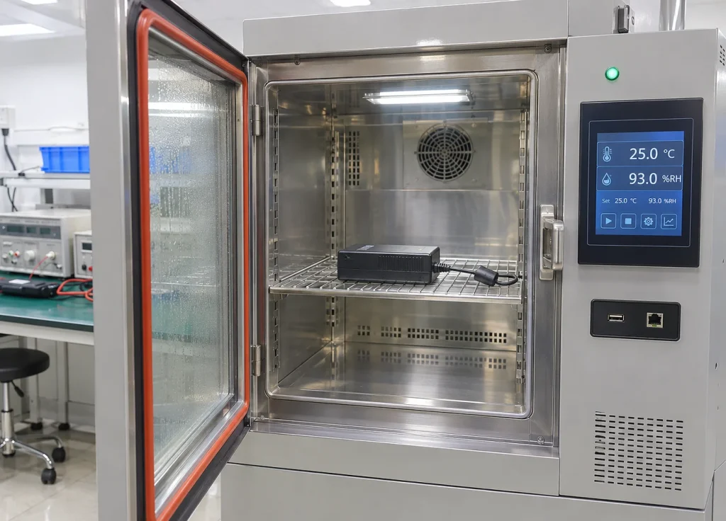
During conditioning, the component or subassembly must not be energized. For general climatic conditions, the air temperature at all sample locations is maintained within ±2°C of a convenient selected value between 20°C and 30°C, with no condensation.
Before humidity conditioning, the sample is brought to a temperature between the selected conditioning temperature and 4°C above that temperature. The subsequent electric strength test must follow the applicable test sequence.
A programmable environmental chamber provides the controlled temperature and humidity conditions required for this type of preparation. For example, KingPo’s 64L Temperature and Humidity Chamber provides a temperature range of -20°C to 150°C and humidity control from 20% to 98% RH, covering the environmental setpoints used in the conditioning profiles described above.
4. Electric Strength Test Procedure – Clause 5.4.9
Selecting the Test Voltage
The test voltage is not a single fixed value for all equipment. It is determined according to the insulation type and the electrical stress conditions specified in IEC 62368-1.
For basic insulation, supplementary insulation and reinforced insulation, Clause 5.4.9.1 identifies three methods for determining the test voltage:
| Method | Basis for Determination |
|---|---|
| Method 1 | Required withstand voltage based on transient voltages from AC mains, DC mains or external circuits (Table 25). |
| Method 2 | Peak working voltage or recurring peak voltage, whichever is higher (Table 26). |
| Method 3 | Nominal AC mains voltage to account for temporary overvoltages (Table 27). |
Unless otherwise specified, the highest test voltage obtained from these three methods is applied. The selected value must also correspond to the insulation category being evaluated.
AC and DC Test Voltage
IEC 62368-1 allows the prescribed test voltage to be applied as either:
- AC voltage: A substantially sinusoidal waveform at 50 Hz or 60 Hz.
- DC voltage: A direct voltage applied for the specified test duration.
Where capacitors are connected in parallel with the insulation under test, such as RF filter capacitors, and these capacitors can affect the test results, DC test voltage must be used.
Components providing a DC current path in parallel with the insulation, such as filter capacitor discharge resistors and voltage-limiting devices, may be disconnected where permitted by the standard.
Applying and Monitoring the Test Voltage
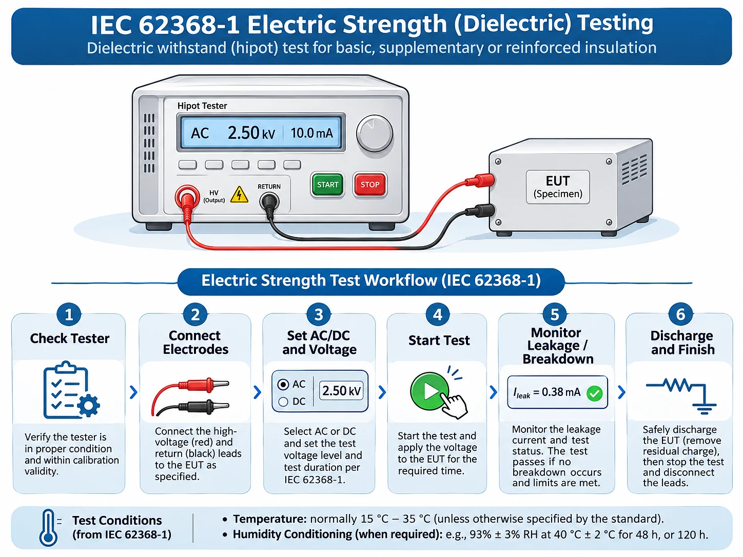
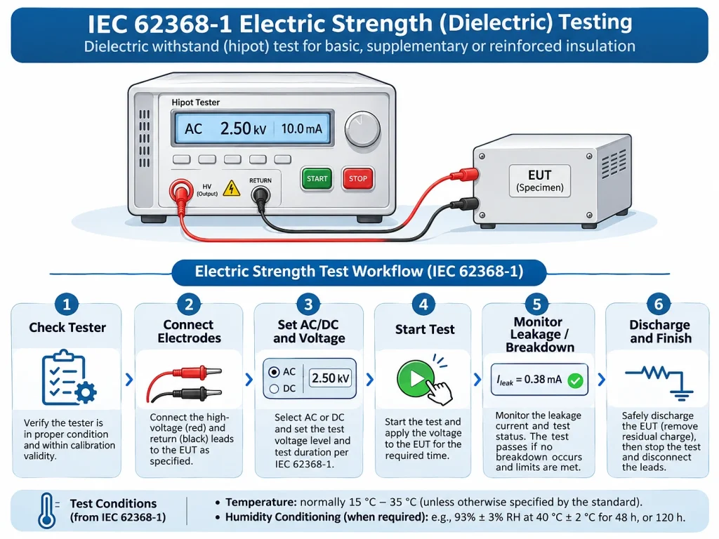
After specimen preparation and voltage selection, the test is carried out using a controlled high-voltage application sequence.
Prepare the specimen
Identify the insulation barrier and confirm the electrode contact positions.
Connect the electrodes
Connect the high-voltage and return electrodes to the appropriate conductive parts.
Configure the tester
Select AC or DC mode and set the prescribed voltage and protection limits.
Raise the test voltage
Gradually increase the voltage from zero to the prescribed test value.
Maintain and monitor
Maintain the prescribed voltage for the required duration while monitoring current behaviour and possible discharge.
Discharge and inspect
Switch off the high-voltage output, discharge the specimen and verify that no residual voltage remains before handling.
Test Duration: Type Testing vs. Routine Testing
The distinction between type testing and routine testing is important when setting the test duration.
| Test Type | Duration | Conditions |
|---|---|---|
| Type test (5.4.9.1) | 60 s | Maintain the prescribed voltage for 60 seconds after gradually raising it from zero. |
| Routine test (5.4.9.2) | 1–4 s | May be conducted at room temperature, and the test voltage may be reduced by 10%. |
A 70-second timer setting may be used in some laboratory operating procedures to allow for voltage ramp-up, but it should not be confused with the 60-second holding time specified for the type test. The ramp-up period and the voltage holding period should be distinguished when configuring the tester.
5. Test Results and Breakdown Criteria
The primary acceptance criterion under Clause 5.4.9 is that no insulation breakdown occurs during the test.
Insulation breakdown is considered to have occurred when the current flowing as a result of the applied test voltage increases rapidly in an uncontrolled manner, indicating that the insulation can no longer restrict current flow.
It is important to distinguish insulation breakdown from other discharge phenomena:
- Insulation breakdown: An uncontrolled increase in current through the insulation. This is considered a failure.
- Corona discharge: Does not, by itself, constitute insulation breakdown.
- Single momentary flashover: A single brief flashover is not regarded as insulation breakdown under the specified compliance criteria.
Acceptance Criterion
The specimen passes when no insulation breakdown occurs during the prescribed test. The current response and discharge behaviour should be evaluated together with the tester’s protection indication.
6. Important Safety Precautions
Electric strength testing involves potentially hazardous high voltage. Safe operation requires appropriate controls before, during and after the test.
- Verify the test connections and protective grounding before applying high voltage.
- Use suitable insulated gloves, protective barriers and other required high-voltage safety equipment.
- Do not touch the specimen, electrodes or test leads while the high-voltage output is energized.
- Disconnect integrated circuits or similar components where necessary to protect components not involved in the test.
- Use equipotential bonding where appropriate to avoid unnecessary electrical stress on unrelated circuits.
- Ensure that the voltage applied to reinforced insulation does not overstress basic or supplementary insulation in parallel arrangements.
- Disconnect components providing a parallel DC path only where permitted by the applicable test procedure.
- After testing, fully discharge the specimen and verify the absence of residual voltage before disconnecting the test leads.
Engineering Takeaways
The reliability of an electric strength test depends on the complete test arrangement, not simply the maximum output voltage of the tester.
For engineers working with IEC 62368-1, the most important points are to identify the correct insulation barrier, establish the required test voltage, apply the appropriate environmental conditioning and follow the specified test sequence.
Particular attention should be given to the relationship between temperature testing under Clause 5.4.1.4, humidity conditioning under Clause 5.4.8 and electric strength testing under Clause 5.4.9. Incorrect specimen preparation or an inappropriate electrode arrangement can lead to misleading test results, even when the tester itself operates normally.
For additional information on the equipment and fixtures used across the standard’s electrical, thermal, mechanical and environmental safety tests, refer to KingPo’s IEC 62368-1 testing and measuring equipment guide.
Reference Standard
IEC 62368-1:2023, Edition 4.0 – Audio/video, information and communication technology equipment – Part 1: Safety requirements.
Relevant clauses: 5.4.1.4, 5.4.8, 5.4.9.1 and 5.4.9.2.