IEC 62368-1:2023 Cord Anchorage and Strain Relief Test: Pull Force, Torque and Cable Protection
Cord anchorage and strain relief are essential safeguards for preventing mechanical stress from reaching electrical connections inside AV and ICT equipment. IEC 62368-1:2023 Annex G addresses not only pull force and torque resistance, but also cord entry protection and bending protection for permanently connected power supply cords.
A cord strain relief test evaluates whether a cable anchorage system can prevent pulling and twisting forces from being transferred to internal electrical terminations. This is important for non-detachable power supply cords and relevant interconnecting cables, particularly those connected to ES2, ES3 or PS3 circuits.
Under IEC 62368-1:2023, the assessment extends beyond mechanical pull testing. Engineers also need to consider supplementary protection at the cord entry and bending protection where applicable.
Scope and Applicable Cables Under IEC 62368-1
IEC 62368-1:2023 Clause G.7.3.1 specifies requirements for cord anchorage and strain relief. The assessment covers non-detachable power supply cords and relevant interconnecting cables.
The clause also addresses safeguards against mechanical strain being transmitted to equipment terminations of conductors in cords or interconnecting cables connected to ES2, ES3 or PS3 circuits.
Non-detachable Power Supply Cords
Permanently connected mains power cords that enter the equipment through a cord anchorage or strain relief structure.
Interconnecting Cables
Relevant interconnecting cables associated with ES2, ES3 or PS3 circuits, where mechanical strain must not compromise their equipment terminations.
Important Engineering Consideration
The evaluation should not be limited automatically to the AC mains input cord. The equipment’s cable connections and energy-source classifications should also be reviewed to identify applicable interconnecting cable safeguards.
How Does Cord Anchorage and Strain Relief Work?
A cord anchorage system mechanically secures a cable where it enters an electrical enclosure. Its primary function is to prevent external pulling, twisting or movement from transferring excessive mechanical stress to internal terminals, solder joints and conductor connections.
A typical assembly may include a cable clamp, retaining bracket, strain relief bushing, cable gland or other mechanical securing structure, depending on the equipment design.
Without effective strain relief, external mechanical loads may be transferred directly to internal conductors. This can cause loose terminals, damaged insulation, broken conductor strands or loss of electrical connections.
The test therefore evaluates the mechanical integrity of the complete cable anchorage arrangement rather than simply checking whether the outer cable jacket remains in position.
Pull Force and Torque Requirements — G.7.3.2.1
IEC 62368-1:2023 specifies a combined linear force and torque assessment for non-detachable power supply cords and cables. The applied linear force is selected according to the mass of the equipment.
Strain Relief Test Force — Table G.8
| Mass of Equipment | Required Pull Force |
|---|---|
| Up to and including 1 kg | 30 N |
| Over 1 kg up to and including 4 kg | 60 N |
| Over 4 kg | 100 N |
IEC 62368-1:2023, Annex G, Table G.8 — Strain relief test force.
Linear Pull Force Application
The specified force is applied to the cord or cable in the most unfavourable direction for 1 second and repeated 25 times.
Torque Application
Immediately after the linear force application, a torque of 0.25 N·m is applied to the cord or cable for 1 minute.
The torque should be applied as close as practicable to the strain relief mechanism. The same torque is then repeated in the opposite direction.
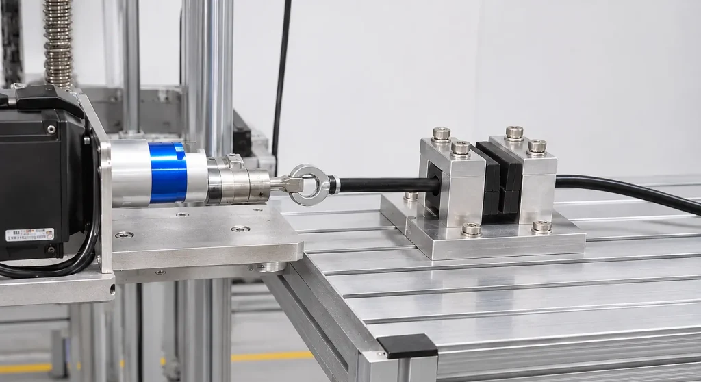
How to Perform the Cord Strain Relief Test
A consistent test setup is important for ensuring that the applied loads are transferred to the intended cable anchorage structure rather than being affected by improper sample positioning or fixture movement.
Test Sequence Matters
The torque application follows the linear force application immediately. The sequence, loading direction, duration and proximity of the torque application to the anchorage should be maintained as specified in G.7.3.2.1.
Acceptance Criteria and Conductor Displacement
Compliance with G.7.3.2.1 is determined through the specified force and torque applications, measurement and visual inspection.
| Inspection Item | Acceptance Requirement |
|---|---|
| Cord condition | No damage to the cord or conductors. |
| Conductor displacement | Not more than 2 mm. |
| Outer jacket movement | Stretching of the outer jacket without conductor displacement is not considered conductor displacement. |
| Internal connections | Inspect relevant terminations and connections for mechanical damage or loss of secure connection. |
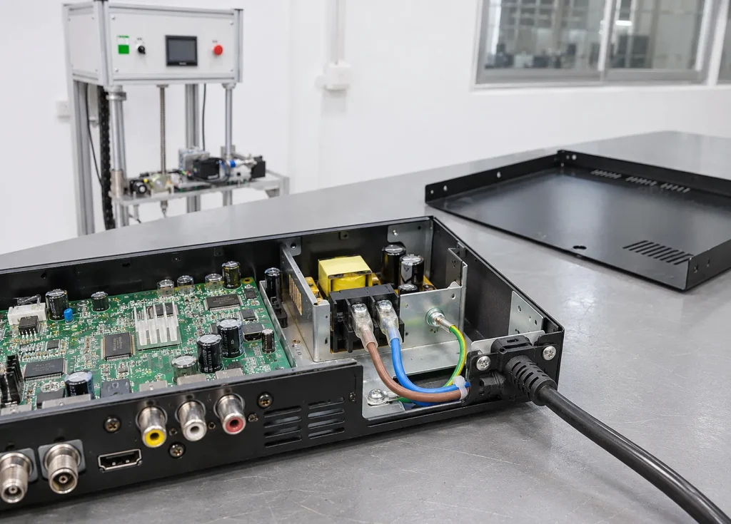
Outer Jacket Movement Is Not the Same as Conductor Displacement
This distinction is explicitly addressed in the standard. A cable jacket may stretch during loading, but this alone does not constitute conductor displacement if the conductors themselves have not moved.
For this reason, visual inspection of the outer cable surface alone is insufficient. The actual position of the conductors and the condition of internal terminations must also be considered.
Additional Cord Anchorage Requirements — G.7.3.2.2 to G.7.3.2.4
In addition to the main pull force and torque test, IEC 62368-1 includes further construction requirements for the strain relief mechanism and cord anchorage.
Strain Relief Mechanism Failure — G.7.3.2.2
If the basic safeguard, such as the strain relief mechanism, fails and mechanical stress is transferred to the cord or cable terminations, a supplementary safeguard must ensure that the protective earth termination is the last connection to take the strain.
Compliance is determined by inspection and, where necessary, by defeating the basic safeguard and examining conductor slack while applying the force specified in Table G.8.
Cord Sheath or Jacket Position — G.7.3.2.3
The cord or cable sheath or jacket must extend from the basic safeguard into the equipment by at least one-half of the cord or cable diameter.
Compliance with this construction requirement is verified by inspection.
Strain Relief and Anchorage Materials — G.7.3.2.4
- The cord anchorage must be made of insulating material or have an insulating lining that complies with basic insulation requirements.
- An exception applies to a bushing that includes the electrical connection to the screen of a screened power supply cord.
- Where the basic safeguard is made of polymeric material, it must retain its structural properties following the mould stress relief test specified in Clause T.8.
- After the basic safeguard returns to room temperature, compliance is determined by inspection and application of the force and torque tests in G.7.3.2.1.
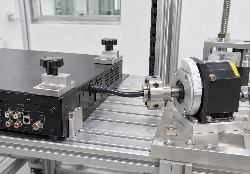
Cord Entry Protection — G.7.4
Cord entry protection is a separate consideration from the mechanical strain relief test. Under G.7.4, the entry of cords or cables connected to ES2, ES3 or PS3 circuits must incorporate appropriate safeguards against electric shock and electrically caused fire.
Protection Against Abrasion
The cord or cable entry must include a supplementary safeguard that prevents the outer surface of the cable from being damaged by abrasion at the equipment opening.
Protection Against Cable Push-In
The entry structure must also prevent the cord or cable from being pushed into the equipment to an extent that could damage the cord, its conductors or both, or displace internal equipment components.
Outer Surface Protection
Protect the cable jacket from sharp edges, friction and abrasion at the entry point.
Mechanical Retention
Prevent excessive inward movement that could damage internal wiring or displace components.
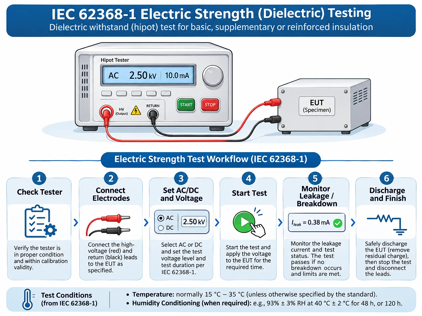
Electric Strength Verification
Following the tests of G.7.3.2.1, compliance is determined by an electric strength test between the cord or cable conductors and accessible conductive parts.
The test voltage must correspond to the requirements for reinforced insulation in accordance with Clause 5.4.9.1.
Important Distinction
G.7.4 specifies a particular electric strength verification after the mechanical tests in G.7.3.2.1. It should not be confused with a blanket requirement to perform an additional insulation resistance test after every cord anchorage test.
Non-Detachable Cord Bend Protection — G.7.5
Cord bending protection addresses a different mechanical risk. When a permanently connected power supply cord is repeatedly bent near the equipment entrance, excessive bending may damage its outer jacket, insulation or conductors.
G.7.5.1 applies this safeguard requirement to non-detachable power supply cords of hand-held equipment and equipment intended to be moved while in operation.
Construction Requirements
The cord bending safeguard must be designed to prevent excessive bending where the cord enters the equipment. It must also meet the following construction requirements:
- Be made of insulating material.
- Be securely fixed to the equipment.
- Protect the cord against excessive bending at the equipment entrance.
- Project outside the equipment beyond the inlet opening by at least five times the cord’s overall diameter.
For flat cords, the required projection distance is at least five times the major overall cross-sectional dimension.
Alternative Construction
The standard also permits an alternative arrangement using a smoothly rounded bell-mouthed inlet or bushing. Its radius of curvature must be at least 1.5 times the overall diameter of the cord with the largest cross-sectional area to be connected.
Test Method — G.7.5.2
The equipment is positioned so that the axis of the cord bending safeguard, at the point where the cord emerges, projects at an angle of 45° when the cord is free from stress.
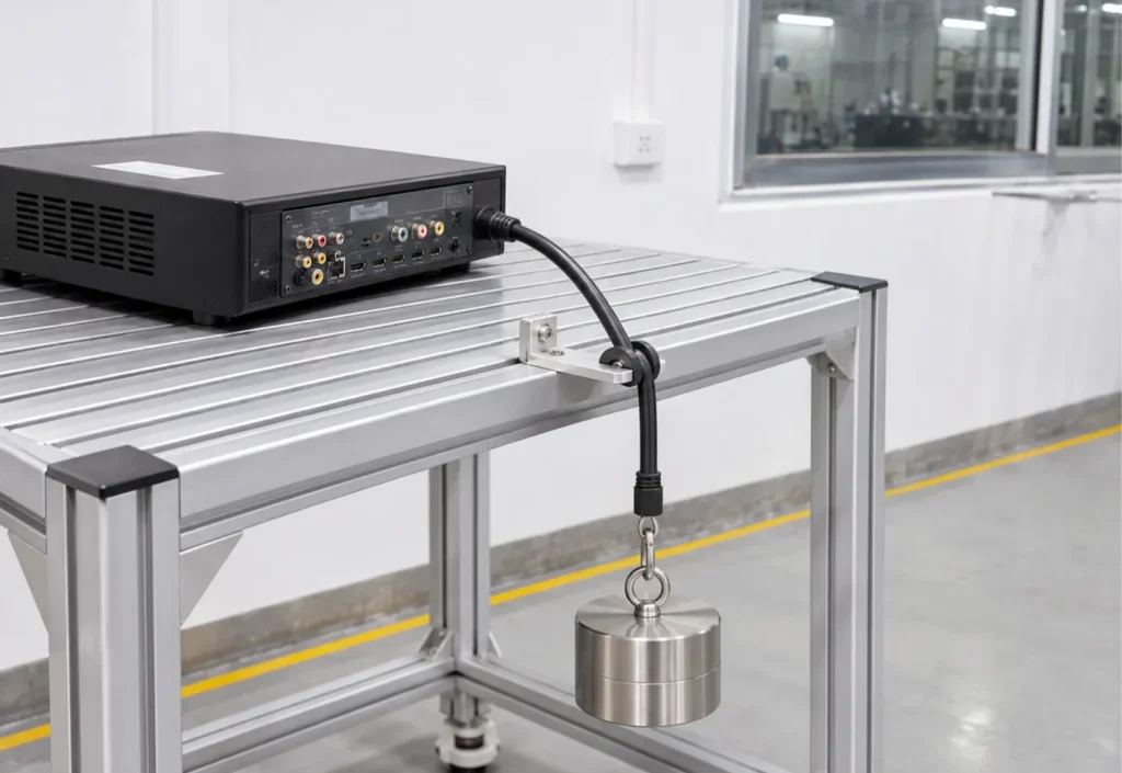
A mass calculated using the cord dimension is then attached to the free end of the cord.
Where:
- D is the overall diameter of a round cord, in millimetres.
- For a flat cord, D is its minor overall dimension, in millimetres.
- The factor 10 is expressed in g/mm².
Round Cord with a 5 mm Diameter
The calculated mass is 250 g. This is an illustrative example; the actual test mass must be calculated using the measured dimension of the cord under evaluation.
Additional Test Conditions
- If the cord guard is made of temperature-sensitive material, the test is performed at 23°C ± 2°C.
- Flat cords are bent in the plane of least resistance.
- Immediately after the mass is attached, the radius of curvature of the cord must nowhere be less than 1.5D.
- Compliance is checked by inspection, measurement and, where necessary, testing with the cord supplied with the equipment.
Do Not Confuse the Two Dimensions for Flat Cords
In G.7.5.1, the projection distance is based on the major overall dimension of a flat cord. In G.7.5.2, the test mass calculation uses the minor overall dimension. These dimensions serve different purposes.
Test Equipment and Laboratory Setup
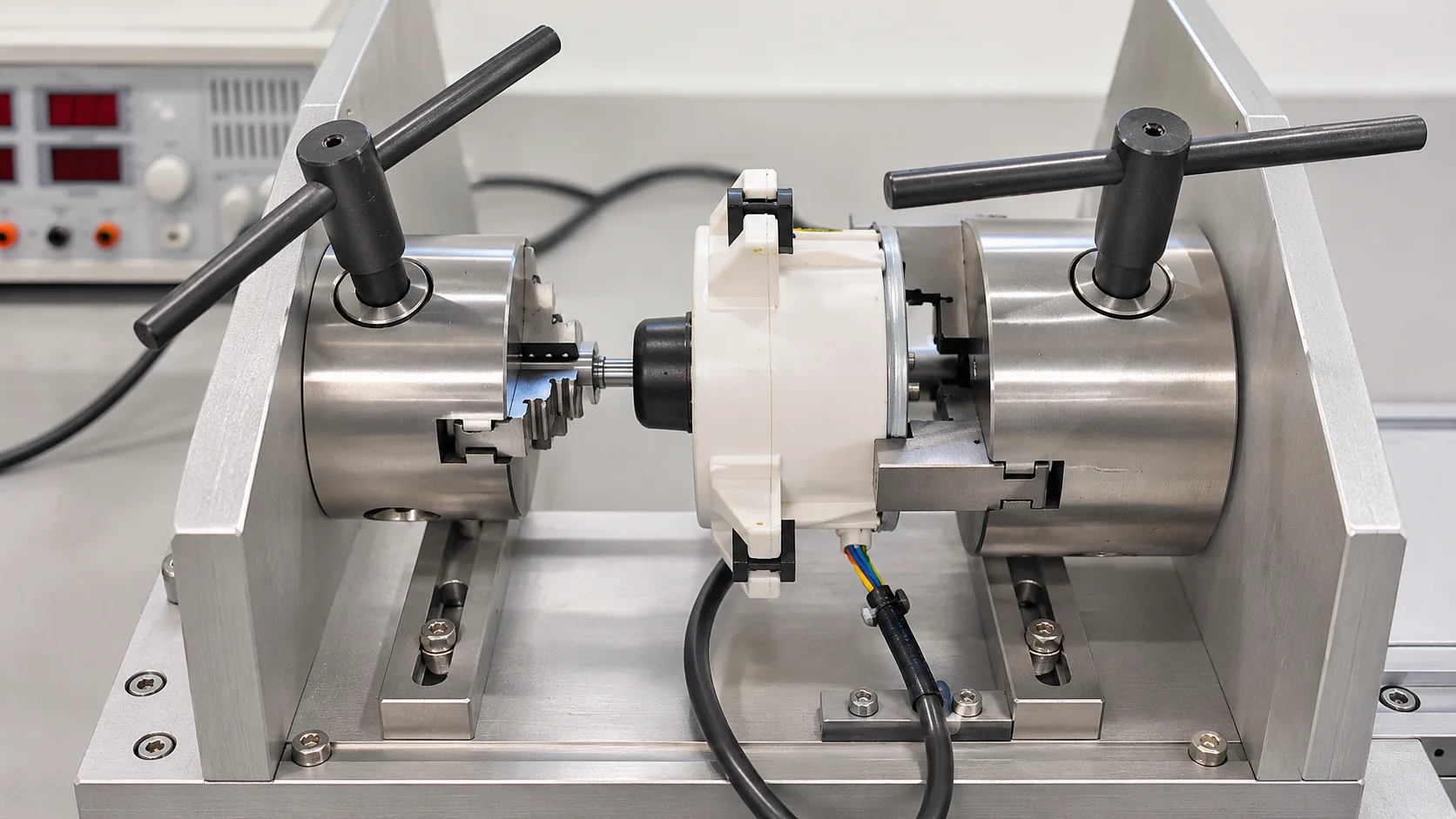
A suitable laboratory arrangement should provide controlled mechanical loading, repeatable positioning and reliable measurement of cable movement. The equipment configuration depends on the applicable test clause and the specimen characteristics.
| Equipment | Purpose | Relevant Test |
|---|---|---|
| Pull force loading system | Apply the specified linear force to the cord. | G.7.3.2.1 |
| Torque application system | Apply 0.25 N·m in the required directions. | G.7.3.2.1 |
| Cable clamping fixture | Secure the cable and maintain the intended loading arrangement. | G.7.3 |
| Caliper or displacement measuring tool | Measure conductor or cable movement where applicable. | G.7.3 |
| Weights and dimensional tools | Establish the required load and cable dimensions. | G.7.5.2 |
| Electric strength tester | Perform the specified electrical verification. | G.7.4 |
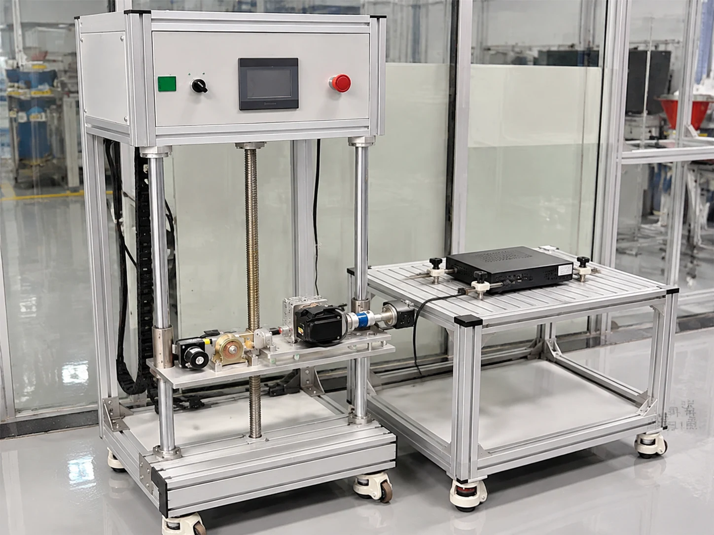
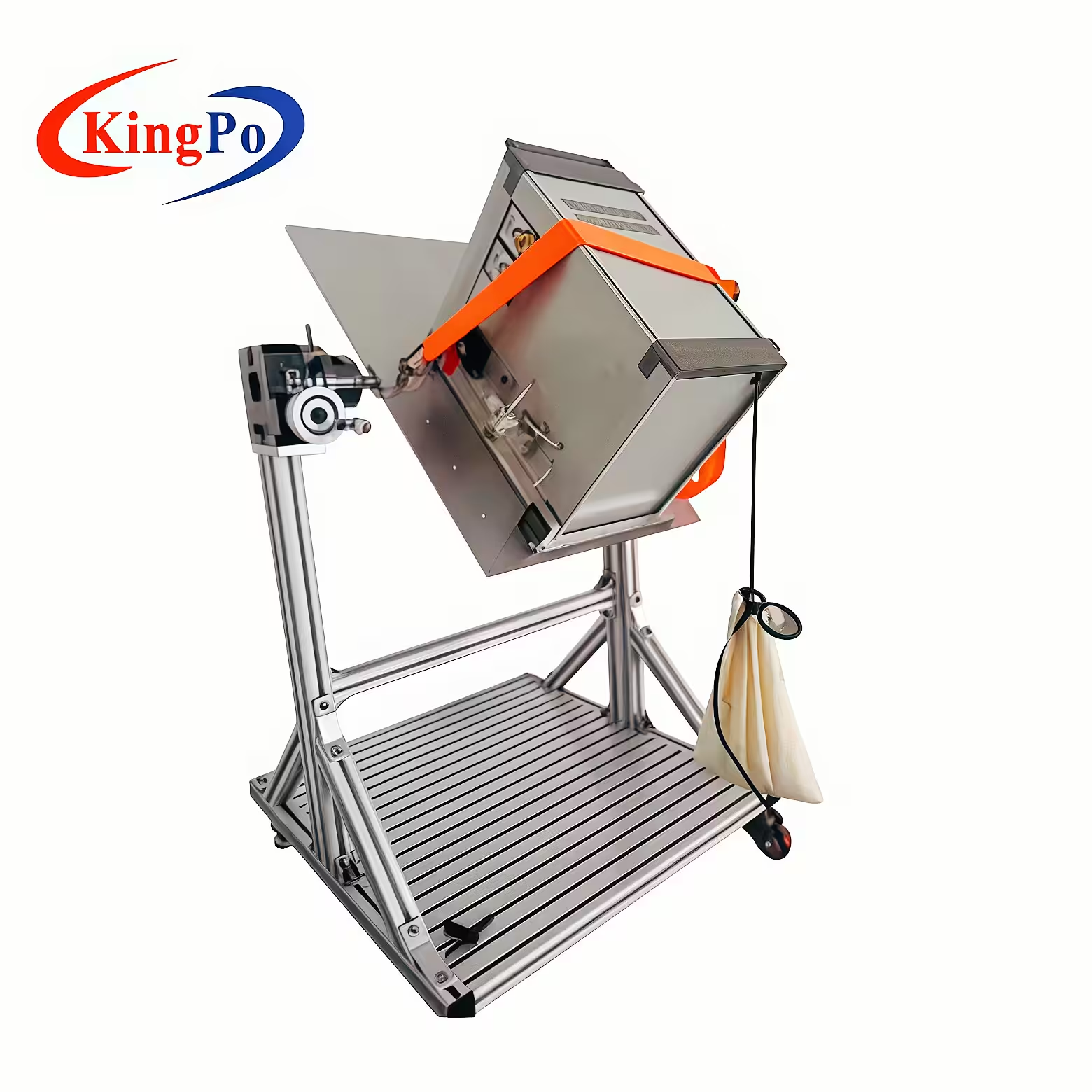
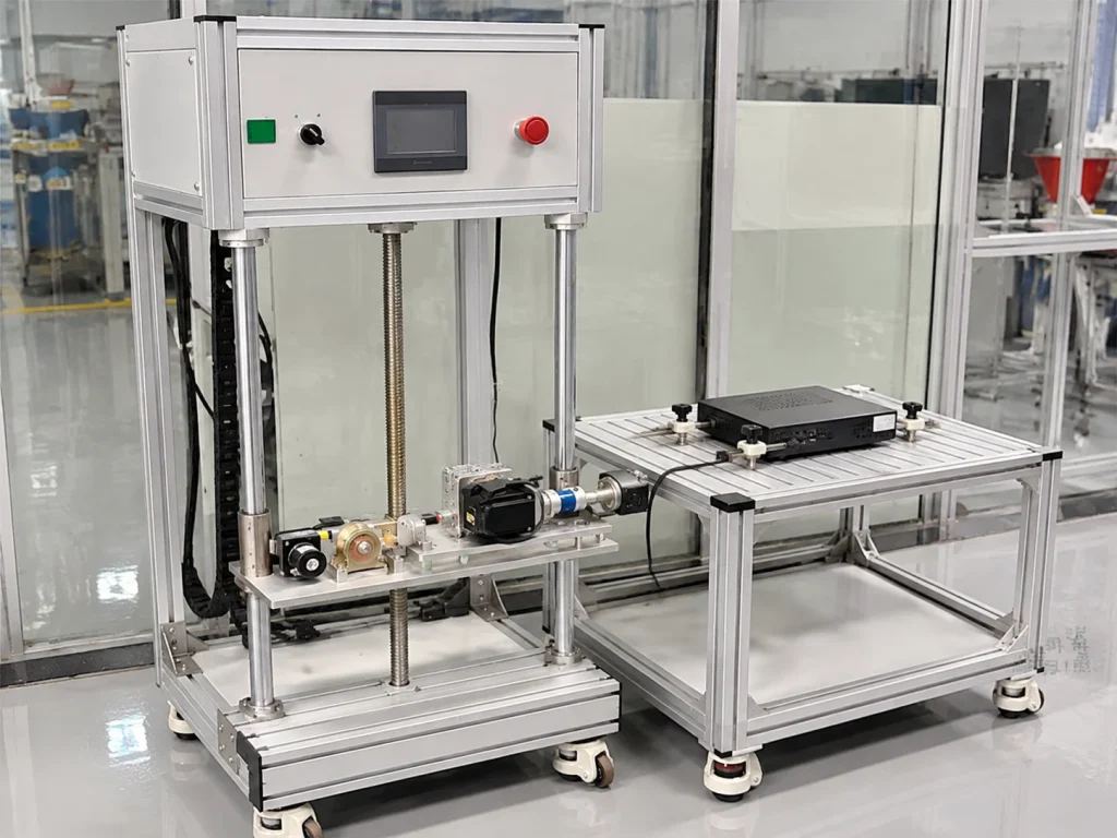
Cord Anchorage Torque Tester
A combined mechanical test arrangement for applying controlled pulling force and torque to power cords.
Equipment Capacity Must Match the Selected Test Condition
The published KingPo tester configuration lists a maximum pull force of 60 N and includes a 0.25 N·m torque option. Table G.8 requires 100 N for equipment weighing over 4 kg. Therefore, specimens in this mass category require a suitable higher-capacity loading configuration. The equipment must also provide the required loading sequence and fixture arrangement.
Common Mistakes in Cord Strain Relief Testing
| Common Mistake | Why It Matters | Engineering Consideration |
|---|---|---|
| Testing only the AC input cord | Relevant interconnecting cables may also fall within G.7.3. | Review cable connections and ES2, ES3 and PS3 classifications. |
| Selecting force only by cable size | Table G.8 determines the linear force according to equipment mass. | Record equipment mass before selecting the test force. |
| Applying torque in only one direction | The specified torque must be repeated in the opposite direction. | Follow the complete torque sequence. |
| Measuring only outer jacket movement | Outer jacket stretching does not necessarily represent conductor displacement. | Evaluate actual conductor movement. |
| Ignoring cord entry protection | A cable may pass mechanical anchorage testing while its entry structure still presents abrasion or push-in risks. | Evaluate G.7.4 separately. |
| Overlooking bending protection | Movement at the cable exit can cause insulation and conductor damage. | Determine whether G.7.5 applies to the equipment. |
Understanding the Complete Cord Protection Assessment
IEC 62368-1:2023 Annex G.7 addresses several aspects of cable protection that should be evaluated according to the equipment construction and applicable requirements.
Evaluates mechanical retention, pull force, torque, conductor displacement and anchorage construction.
Addresses electrical safeguards, abrasion prevention and protection against excessive inward cable movement.
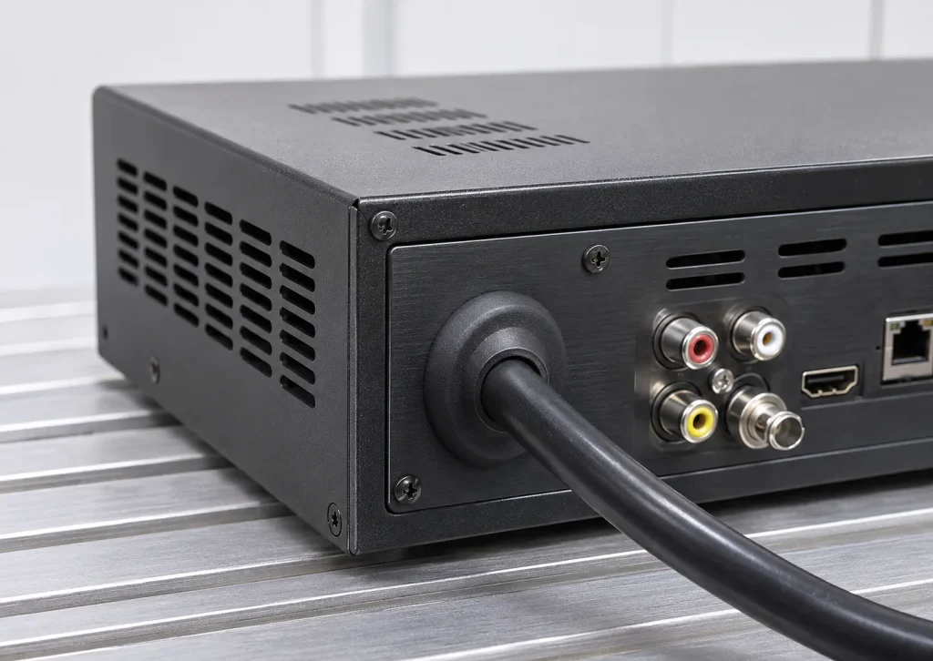
Evaluates the construction and bending resistance of applicable permanently connected power supply cords.
For AV and ICT equipment manufacturers, these requirements provide a practical framework for evaluating cable retention, insulation protection and the reliability of internal electrical connections under mechanical stress.
Applicable Standard and Further Reading
IEC 62368-1:2023 — Edition 4.0
Audio/video, information and communication technology equipment — Part 1: Safety requirements.
Relevant provisions discussed in this article:
- G.7.3 — Cord anchorages and strain relief
- G.7.3.2.1 — Pull force and torque requirements
- G.7.3.2.2 to G.7.3.2.4 — Additional anchorage requirements
- G.7.4 — Cord entry
- G.7.5 — Non-detachable cord bend protection
- 5.4.9.1 — Electric strength test
- T.8 — Mould stress relief
IEC Official Standard Publication →
For further information about testing equipment used in AV and ICT safety evaluations, visit the IEC 62368-1 Test Equipment Guide.
KINGPO develops and manufactures electrical safety testing equipment and customized laboratory test systems for product manufacturers, testing laboratories and certification organizations.
IEC 62368-1:2023, Edition 4.0, Annex G.7.3 to G.7.5, Clause 5.4.9.1 and Clause T.8.This article is a technical overview of selected requirements. The complete standard, applicable amendments and national or regional adoptions should be consulted when determining product conformity.