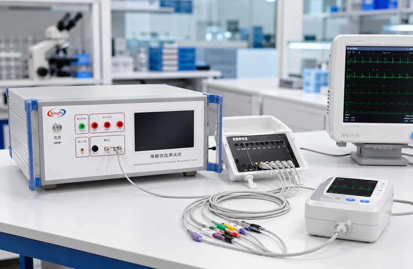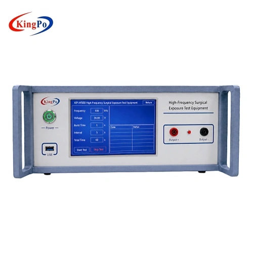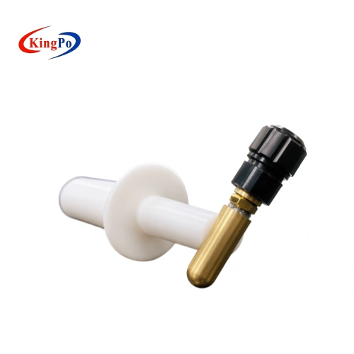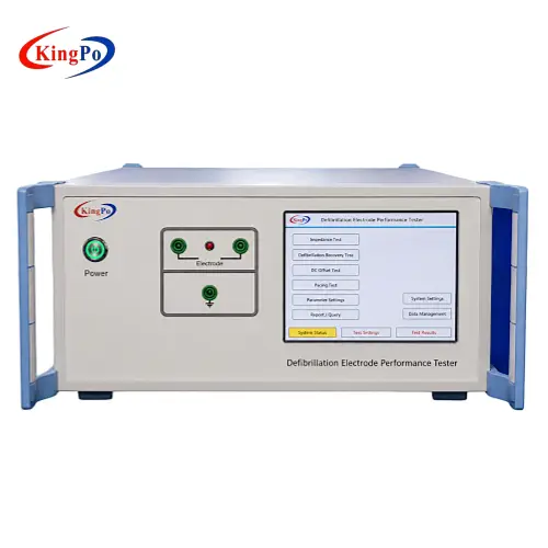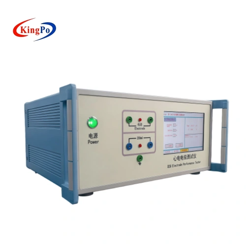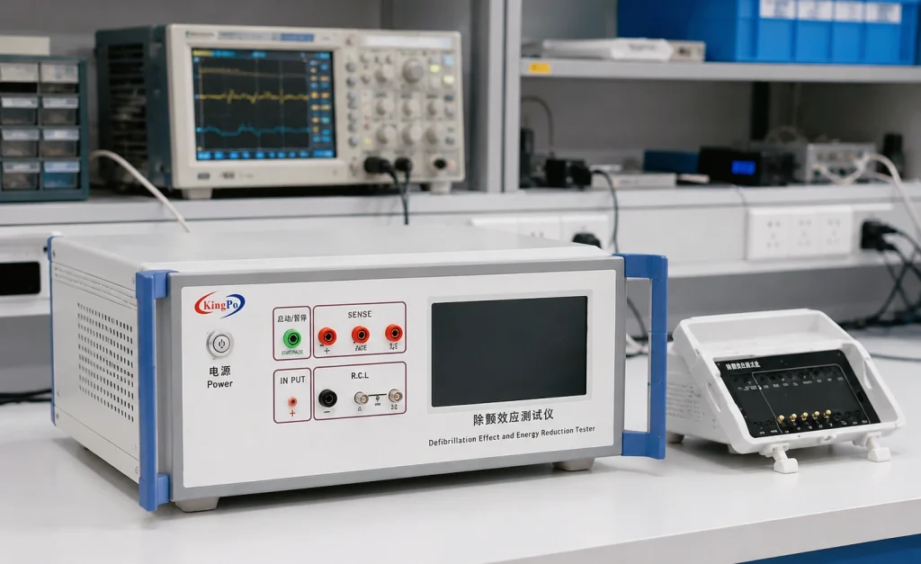
Medical electrical equipment that remains connected to a patient during defibrillation can be exposed to a high-voltage pulse through its patient connections. For equipment incorporating a DEFIBRILLATION-PROOF APPLIED PART, IEC 60601-1 addresses both protection against the effects of defibrillation and the amount of defibrillation energy that remains available through the patient connection.
A Defib-proof and Energy Reduction Tester provides the controlled high-voltage source, test networks, polarity selection and measurement functions required to reproduce these laboratory conditions. The test is commonly relevant to ECG monitors, electrocardiographs, multiparameter patient monitors and other medical electrical equipment incorporating defibrillation-proof patient connections.
This guide explains what IEC 60601 defibrillation-proof testing actually evaluates, how energy reduction testing works, why the frequently quoted “400 J to 360 J” explanation is incomplete, and how the KingPo KP3301/KP3301B can be integrated into a repeatable laboratory test workflow.
IEC 60601-1 Clause 8.5.5 addresses DEFIBRILLATION-PROOF APPLIED PARTS. The requirements include protection of the equipment during exposure to a defibrillation-related test condition and evaluation of the defibrillation energy delivered through the patient connection. These tests are related, but they do not evaluate exactly the same characteristic of the DUT.
Key Takeaways
- Defibrillation-proof testing is more than a simple high-voltage withstand test.
- The applied-part classification and patient connection arrangement determine how the test should be configured.
- Energy reduction testing evaluates whether the DUT excessively reduces the defibrillation energy available through the specified load.
- The energy result should be evaluated by comparing the measurement with the DUT connected against the appropriate reference condition.
- A value such as 360 J should not be treated as a universal standalone IEC 60601 pass/fail limit.
IEC 60601-1 and Defibrillation-Proof Applied Parts
IEC 60601-1 establishes general requirements for the basic safety and essential performance of medical electrical equipment. Within the standard, special requirements apply where an APPLIED PART is intended to remain connected to the patient when defibrillation may occur.
This situation is important because a therapeutic defibrillator can introduce a short-duration, high-voltage electrical condition through ECG electrodes, monitoring leads or other PATIENT CONNECTIONS. The equipment therefore needs appropriately designed isolation, protective components and input circuitry.
The purpose of the compliance test is not simply to determine whether a PCB survives a high-voltage pulse. The evaluation considers whether the defibrillation event can create an unacceptable electrical hazard, interfere with the intended protection of the patient, or leave the equipment in an unacceptable condition.
The applicable IEC 60601 or IEC 80601 particular standard should always be checked in addition to IEC 60601-1. Particular standards can supplement or modify the general test arrangement, recovery requirement or performance criteria for a specific type of medical equipment.
What Is Defibrillation-Proof Testing?
A medical device may remain electrically connected to the patient when an external defibrillator delivers a shock. The resulting electrical stress can reach the patient input circuitry through ECG electrodes and other patient connections.
For an APPLIED PART classified as defibrillation-proof, the protection design must prevent the defibrillation event from creating unacceptable hazards in other accessible or patient-connected parts of the equipment.
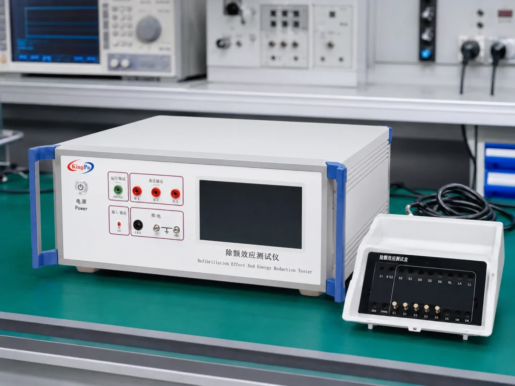
Depending on the applicable test arrangement and equipment type, the laboratory evaluation may involve:
- electrical isolation of the patient-connected input circuitry;
- high-voltage stress applied through specified patient connections;
- common-mode or bridged patient-connection conditions;
- individual or differential patient-connection conditions;
- measurement of hazardous or residual voltage;
- evaluation of the equipment after exposure;
- verification of required BASIC SAFETY and ESSENTIAL PERFORMANCE.
IEC 60601-1 Clause 8.5.5: Two Different Test Objectives
A common mistake is to treat defibrillation-proof testing and energy reduction testing as the same measurement. They are closely related, but the engineering questions are different.
| Test Area | Engineering Question | Typical Evaluation |
|---|---|---|
| Clause 8.5.5.1 Defibrillation-proof protection |
Can the patient-connected circuitry withstand the specified defibrillation-related electrical stress without creating an unacceptable hazard? | Patient connections, insulation, hazardous voltage, equipment condition and required recovery. |
| Clause 8.5.5.2 Delivered defibrillation energy |
Does connecting the ME EQUIPMENT reduce the defibrillation energy available through the defined test circuit excessively? | Comparison between the energy measured with the DUT connected and the corresponding reference condition. |
Common-Mode and Differential-Mode Testing
IEC 60601-1 uses different connection arrangements depending on the patient connections being evaluated. In laboratory practice, these are commonly described as common-mode and differential-mode defibrillation tests.
For equipment with multiple ECG leads, some patient connections may need to be bridged together while another connection or lead group is tested separately. The exact lead configuration needs to follow the applicable standard and the DUT design.
This is one reason automated patient-lead switching can be valuable for multi-lead ECG monitors and electrocardiographs. It reduces repeated manual rewiring while preserving a defined and repeatable test sequence.
How the Energy Reduction Test Actually Works
The term energy reduction is frequently misunderstood. The purpose is not simply to demonstrate that a nominal 400 J pulse becomes 360 J after passing through the equipment.
Instead, the test evaluates whether the ME EQUIPMENT and its patient-connected circuitry absorb, divert or attenuate too much of the defibrillation energy that would otherwise be available through the specified test load.
The measurement therefore uses a reference comparison.
| Measurement | Meaning |
|---|---|
| E1 | Energy delivered to the specified test load with the ME EQUIPMENT connected in the prescribed test configuration. |
| E2 | Reference energy delivered to the corresponding load when the ME EQUIPMENT is removed from the specified comparison condition. |
This comparison is the important engineering principle. A measured value such as 360 J does not, by itself, demonstrate compliance. The measurement must be interpreted against the corresponding reference energy and the specified electrical test network.
Do not present “400 J reduced to 360 J” as the IEC 60601 test requirement. A value near this range may be associated with particular theoretical or circuit conditions, but the compliance concept is based on the defined reference comparison.
Why the Test Network Matters
A defibrillation test condition is defined by more than peak voltage. Capacitance, resistance, inductance, switching conditions and the measurement load determine the waveform and energy delivered to the DUT.
For the energy reduction function, the laboratory setup incorporates the specified load network and a 25 mH inductive condition. Energy can be determined from the voltage measured across the defined resistance using the relationship:
The important point is not the mathematical expression alone. Engineers also need to verify that the correct resistance, inductance, polarity, patient connections and measurement point have been selected before the result is considered meaningful.
KP3301/KP3301B Defib-proof and Energy Reduction Tester
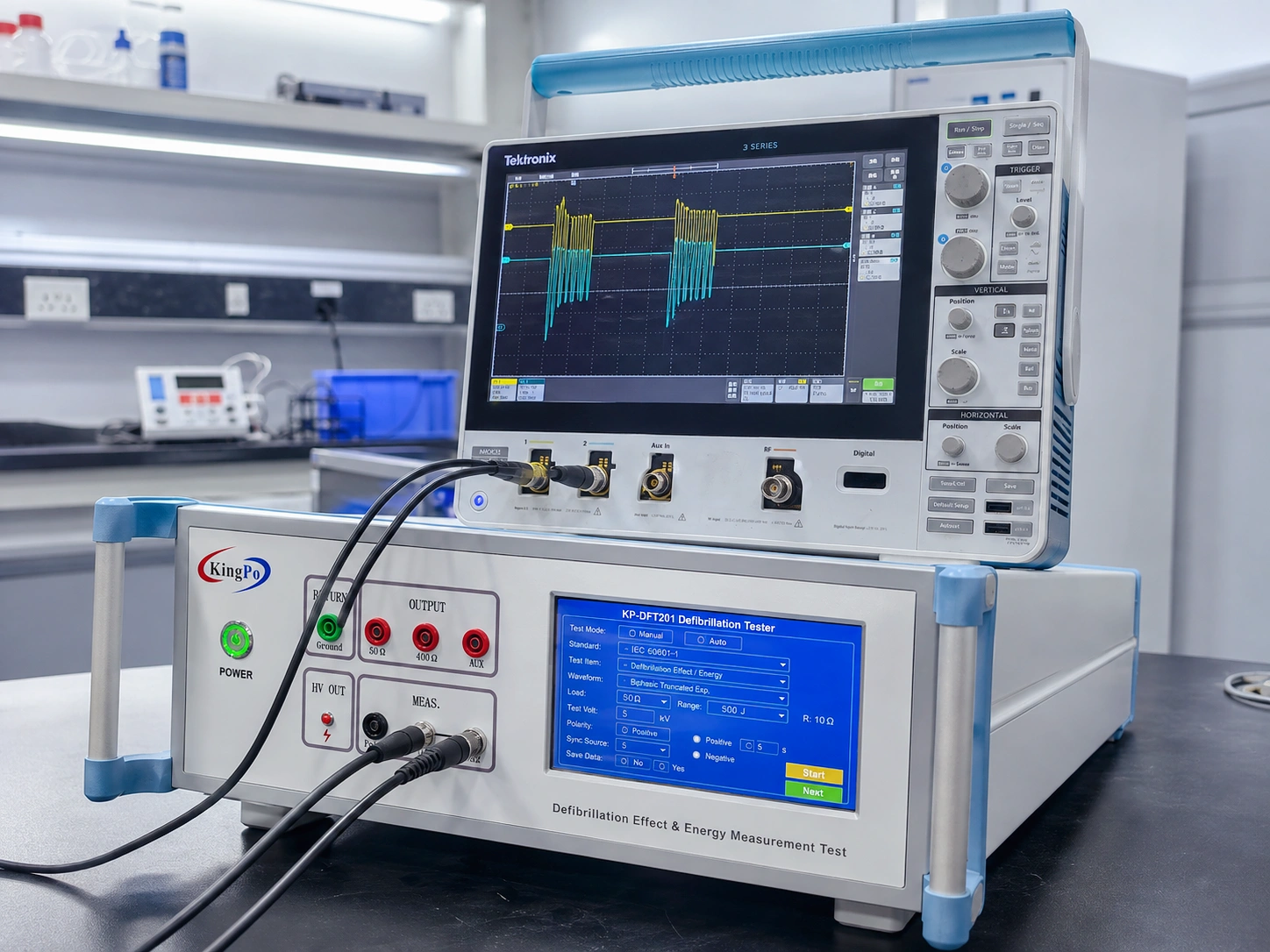
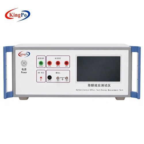
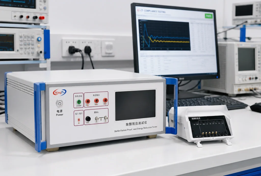
The KingPo KP3301/KP3301B Defibrillation Effect & Energy Tester integrates the high-voltage pulse source, selectable test network, polarity control and measurement functions required for this type of laboratory evaluation.
The system is designed to reduce the amount of external wiring required when configuring defibrillation-proof and energy reduction tests on compatible patient-connected medical electrical equipment.
| Function | KP3301/KP3301B Capability |
|---|---|
| High-voltage output | Up to ±5.5 kV |
| Polarity | Positive and negative test conditions |
| Resistance / inductance | Selectable network configuration for different test arrangements |
| Energy reduction mode | Supports the 25 mH energy-test condition and automatic energy calculation |
| Energy display | 1 J display resolution |
| Control interface | 7-inch LCD touchscreen |
| Patient-lead switching | KP3301 manual configuration; KP3301B supports automated lead switching |
| Applications | ECG monitors, electrocardiographs, patient monitors and related defibrillation-proof applied-part testing |
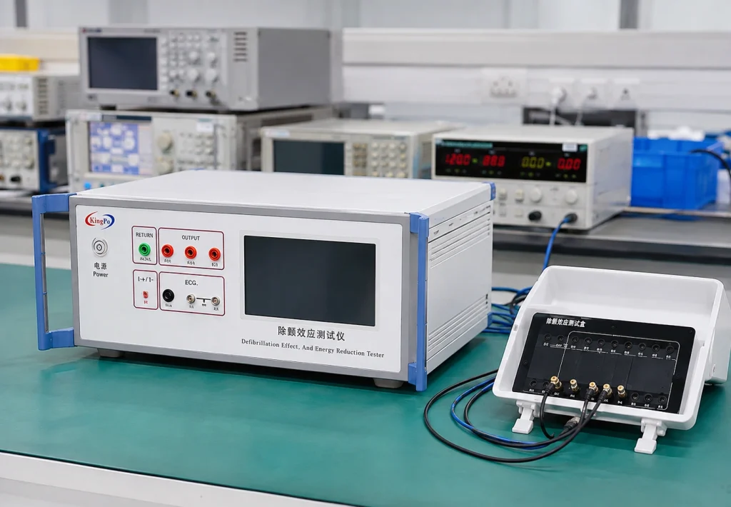
Before selecting the tester configuration, confirm the applicable IEC clause, DUT type, APPLIED PART classification, number of patient leads and whether manual or automatic lead switching is required.
Defibrillation Test Demonstration
The following demonstration shows the operating concept of the defibrillation test system and the type of laboratory setup used during patient-connected medical equipment evaluation.

Step-by-Step Defibrillation Test Workflow
A reliable test starts with the DUT classification and applicable standard rather than with the tester settings. A practical laboratory workflow is shown below.
Common Mistakes in Defibrillation and Energy Reduction Testing
1. Treating 360 J as the Pass/Fail Requirement
A value around 360 J can appear under particular theoretical test-network conditions, but it should not be treated as a universal acceptance value. Energy reduction is fundamentally a comparison between the defined DUT-connected condition and the corresponding reference condition.
2. Using the Wrong Patient-Lead Configuration
Multi-lead ECG equipment can have many PATIENT CONNECTIONS. Applying the test to the wrong lead group, incorrectly bridging the leads or failing to connect the remaining leads as required can change the electrical test condition.
3. Confusing Defibrillation Withstand with Energy Reduction
A DUT can survive a high-voltage pulse while still influencing the energy delivered through the patient connection more than permitted. Conversely, an acceptable energy comparison alone does not demonstrate every aspect of defibrillation-proof protection.
4. Ignoring Test Polarity
Protection devices such as diodes, transient suppressors and semiconductor input networks can respond differently to positive and negative stress. Required polarity reversal should therefore not be omitted.
5. Checking Only Whether the Equipment Still Powers On
Physical survival is not the same as compliance. Engineers should define the required post-test operating condition and determine whether the relevant BASIC SAFETY and ESSENTIAL PERFORMANCE functions recover as required.
6. Using a Generic High-Voltage Generator Without Verifying the Test Network
Peak voltage alone does not reproduce a defibrillation test condition. Resistance, capacitance, inductance, switching and measurement points all affect the energy and waveform experienced by the DUT.
Which Medical Devices May Require Defibrillation-Proof Testing?
Defibrillation-proof testing is relevant where the device design, APPLIED PART classification and applicable standard require the patient-connected circuitry to tolerate defibrillation-related electrical conditions.
Typical products may include:
- electrocardiographs;
- ECG monitors;
- multiparameter patient monitors;
- ECG modules integrated into medical systems;
- patient-monitoring systems using defibrillation-proof applied parts;
- other medical electrical equipment specifically designed with defibrillation-proof patient connections.
A patient connection by itself does not automatically mean that Clause 8.5.5 testing applies. Confirm the APPLIED PART classification and applicable particular standard before defining the test plan.
Defib-proof Tester vs Defibrillator Analyzer
These instruments are often confused because both are associated with defibrillation energy, but they perform different jobs.
| Equipment | Primary Function |
|---|---|
| Defib-proof and Energy Reduction Tester | Applies controlled defibrillation-related electrical conditions to patient-connected medical equipment to evaluate protection and energy reduction. |
| Defibrillator Analyzer | Measures the energy, waveform and other output characteristics produced by an actual clinical defibrillator. |
The KP3301/KP3301B belongs to the first category. It is intended to reproduce compliance-related electrical test conditions for the DUT rather than primarily measuring the therapeutic output of a clinical defibrillator.
FAQ
What is a Defib-proof and Energy Reduction Tester?
It is a laboratory test system that applies controlled defibrillation-related high-voltage conditions to compatible patient-connected medical electrical equipment and supports evaluation of protection against defibrillation and delivered-energy reduction.
Which IEC 60601-1 clause covers defibrillation-proof applied parts?
IEC 60601-1 Clause 8.5.5 addresses DEFIBRILLATION-PROOF APPLIED PARTS, including requirements related to protection against defibrillation and delivered defibrillation energy.
What is the purpose of energy reduction testing?
The purpose is to determine whether the ME EQUIPMENT and its patient-connected circuitry reduce the defibrillation energy available through the specified test load excessively.
Does IEC 60601-1 simply require 400 J to become 360 J?
No. The important evaluation compares the energy measured with the DUT connected against the corresponding reference energy. A value around 360 J is not a universal standalone acceptance limit.
What does E1 ≥ 90% × E2 mean?
E1 represents the energy obtained under the DUT-connected condition and E2 represents the corresponding reference condition. The comparison determines whether the patient-connected equipment has reduced the available defibrillation energy excessively.
Why are positive and negative test polarities required?
Input-protection components can behave differently under opposite polarities. Where required by the test procedure, both polarity conditions need to be evaluated.
What is the difference between KP3301 and KP3301B?
The KP3301 supports the required defibrillation test functions with manual lead configuration. The KP3301B adds an automatic lead-switching arrangement that is particularly useful for multi-lead ECG equipment.
Can the tester be used for every patient-connected medical device?
No. Applicability depends on the equipment type, APPLIED PART classification, intended use and applicable IEC 60601 or IEC 80601 particular standard.
Why is patient-lead mapping important?
The electrical stress applied to the DUT depends on which patient connections are bridged, isolated, grounded or individually tested. Incorrect lead mapping can therefore create the wrong test condition.
What information should be provided before ordering the tester?
Provide the applicable IEC standard and clause, DUT type, APPLIED PART classification, patient-lead configuration, number of patient connections, required test modes and whether automatic lead switching is required.
KingPo can review the applicable IEC clause, patient-lead configuration and DUT type before recommending the KP3301/KP3301B configuration. Providing this information before quotation helps avoid incorrect adapters, lead converters or test-network configurations.
Conclusion
IEC 60601 defibrillation testing should be treated as a controlled medical electrical safety evaluation rather than as a generic high-voltage withstand test. Correct patient-lead configuration, test-network parameters, polarity and measurement points all influence the validity of the result.
For energy reduction testing, the most important point is also the easiest to misunderstand: the test is not simply asking whether a nominal 400 J becomes 360 J. The relevant evaluation compares the energy obtained with the DUT connected against the corresponding reference condition.
The KingPo KP3301/KP3301B Defib-proof and Energy Reduction Tester combines the high-voltage source, selectable electrical network, polarity control, energy measurement and patient-lead switching functions needed to make these test workflows more repeatable.
Before testing, always confirm the applicable standard, clause, APPLIED PART classification and patient connection arrangement for the specific DUT.