
IEC 60601-2-2 NE Contact Impedance Tester
A neutral electrode provides the return path for high-frequency surgical current. In addition to the characteristics of the electrode application surface, the electrical connection between the conductive electrode area and its cable can influence the effective impedance of the return path.
Excessive electrical contact impedance can increase resistive heating when high-frequency surgical current passes through the connection. For this reason, the applicable neutral electrode test method evaluates whether the electrical connection remains sufficiently low in impedance across the specified high-frequency range.
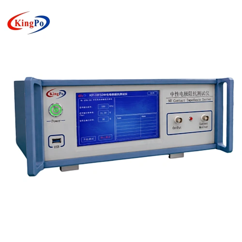
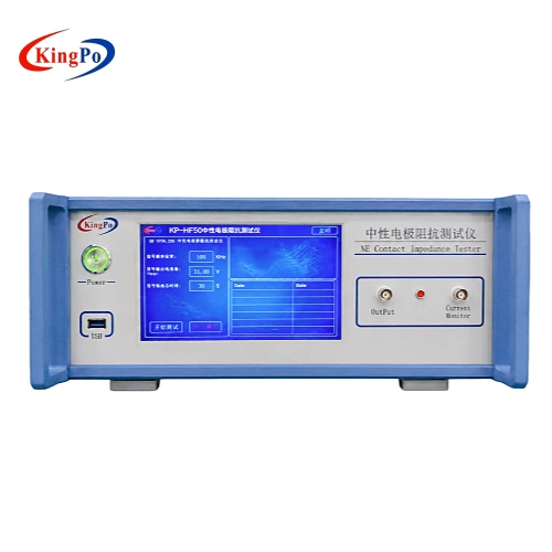
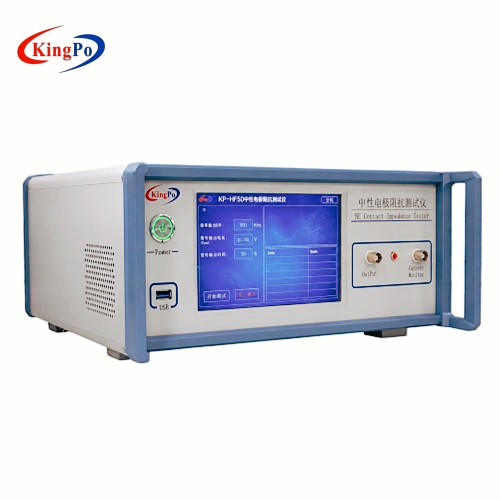
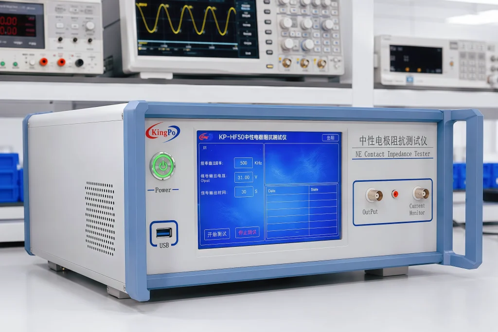
The KP-HF50 provides the high-frequency signal source and measurement interface required for this evaluation. Instead of functioning as a general-purpose electrosurgical unit analyzer, it is dedicated to neutral electrode contact impedance testing.
For conductive neutral electrodes, the measured RMS voltage and current are used to calculate contact impedance. For capacitive neutral electrodes, the same high-frequency measurement data can be used to calculate contact capacitance.
This focused test architecture makes the KP-HF50 suitable for product development, type testing, quality verification and laboratory evaluation of neutral electrodes.
Technical Specifications
| Item | Specification |
|---|---|
| Model | KP-HF50 |
| Applicable Standard | GB 9706.202-2021 / IEC 60601-2-2:2017 |
| Test Item | Neutral electrode contact impedance |
| Signal Waveform | Sine wave |
| Standard Test Frequencies | 200 kHz, 500 kHz, 1 MHz, 2 MHz, 5 MHz |
| Frequency Accuracy | ≤ ±0.1% |
| Maximum Output Voltage | 12 Vrms (approximately 36 Vpp), ≥50 Ω load |
| Maximum Current | >200 mA RMS, ≤50 Ω load |
| Current Measurement Accuracy | < ±5% |
| Current Measurement Frequency Range | 50 kHz to 5 MHz |
| Output Interface | BNC |
| Control Mode | Touchscreen control / PC control |
| PC Test Software | Optional |
| Power Supply | AC 100–220 V ±10%, 50/60 Hz |
| Dimensions | 320 × 260 × 150 mm |
| Weight | Approx. 2 kg |
What the KP-HF50 Evaluates
The KP-HF50 is intended to evaluate the electrical connection between the neutral electrode conductive surface and the neutral electrode cable connection near the electrode.
Two types of neutral electrode behavior can be evaluated.
Conductive Neutral Electrodes
For a conductive neutral electrode, the system measures the effective high-frequency test voltage and current and determines the electrical contact impedance:
Where:
- Zc = contact impedance, Ω
- Utest = RMS high-frequency test voltage, V
- Itest = RMS high-frequency test current, A
For the test method referenced in the supplied technical documentation, the contact impedance of a conductive neutral electrode is evaluated against a 50 Ω limit over the applicable high-frequency range.
Capacitive Neutral Electrodes
For a capacitive neutral electrode, the test evaluates the effective capacitance of the electrical connection.
The contact capacitance can be calculated from:
Where:
- Cc = contact capacitance, nF
- Itest = RMS high-frequency test current, A
- ftest = high-frequency test frequency, kHz
- Utest = RMS high-frequency test voltage, V
For the referenced test method, capacitive neutral electrodes are evaluated against a minimum contact capacitance of 4 nF.
This distinction is important because conductive and capacitive neutral electrodes cannot be assessed using the same electrical parameter alone.
IEC 60601-2-2 Contact Impedance Test Method
The contact impedance test is performed using the neutral electrode, a conductive metal plate, the KP-HF50 high-frequency signal source and appropriate RMS measurement equipment.
A typical laboratory procedure follows this sequence:
- Place the complete application surface of the neutral electrode securely against a conductive metal plate.
- Connect the measurement circuit between the metal plate and the neutral electrode cable conductor.
- Apply an approximately sinusoidal high-frequency test current through the electrode connection.
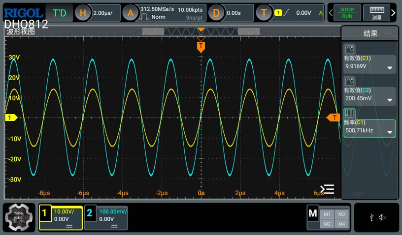
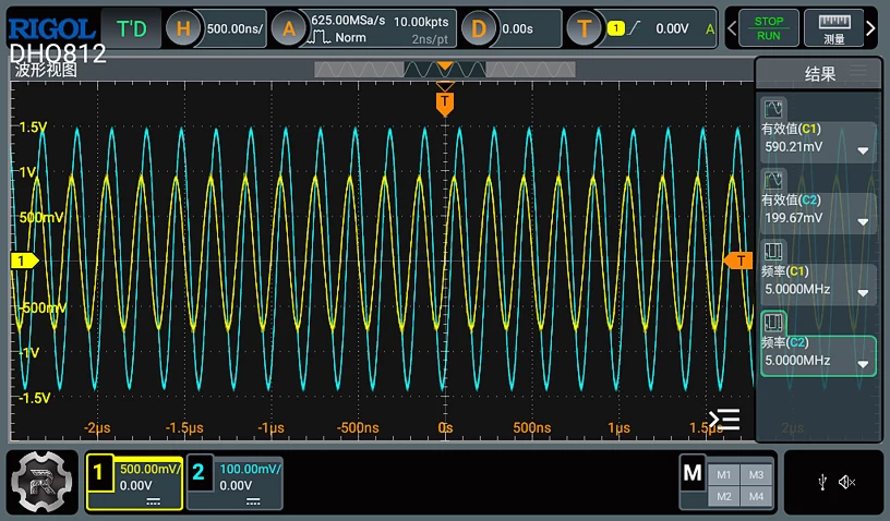
- Monitor the RMS test voltage and RMS test current.
- Record the voltage and current at the required test frequencies.
- Calculate the contact impedance for conductive electrodes.
- Calculate contact capacitance where the DUT is a capacitive neutral electrode.
- Compare the calculated result with the acceptance criteria of the applicable standard and test plan.
The supplied test documentation identifies the following principal measurement frequencies:
- 200 kHz
- 500 kHz
- 1 MHz
- 2 MHz
- 5 MHz
The referenced procedure also calls for multiple neutral electrode samples rather than relying on the result from a single specimen. The exact sample quantity, conditioning and acceptance criteria should always be confirmed against the applicable standard edition and laboratory test procedure.
Why High-Frequency Measurement Matters
Neutral electrodes operate in a high-frequency electrosurgical environment. A resistance measurement made only with DC or a conventional low-frequency ohmmeter does not reproduce the electrical conditions considered by the high-frequency contact impedance test.
The KP-HF50 therefore generates a controlled sine-wave test signal across the required high-frequency measurement points and provides sufficient current for the neutral electrode test circuit.
A DDS-based signal generation architecture is used to provide programmable high-frequency sine-wave output, while the integrated control system allows frequency and output conditions to be set from the touchscreen.
For laboratories, this provides a more repeatable workflow than assembling a test from a general-purpose low-power signal generator that may not be capable of supplying the required HF current into the test load.
Touchscreen Operation
The front-panel color touchscreen allows the operator to set and review the principal operating parameters directly on the instrument.
The interface is intended for laboratory use where engineers need to move between multiple high-frequency test points without repeatedly reconfiguring separate signal-generation equipment.
Depending on the selected test procedure, the operator can configure the signal output, observe instrument status and perform the required test sequence from the touchscreen.
For laboratories requiring higher test throughput or more standardized reporting, the KP-HF50 can also be configured with PC-based test software.
Optional Automated Test Software
The optional PC software extends the KP-HF50 from a manually controlled HF source into a more automated neutral electrode test system.
Automatic Frequency Switching
The software can control the KP-HF50 output and automatically switch between the required test frequencies during the measurement sequence.
This is particularly useful when testing the same neutral electrode at 200 kHz, 500 kHz, 1 MHz, 2 MHz and 5 MHz.
Adaptive Output Adjustment
The system can adjust the output voltage according to the measured current so that the required test condition can be established more efficiently.
Oscilloscope Data Acquisition
Where a compatible measurement arrangement is used, the software can acquire RMS voltage and RMS current data from the oscilloscope instead of requiring the engineer to record every reading manually.
Automatic Impedance and Capacitance Calculation
Measured voltage and current data can be used automatically to calculate:
- Neutral electrode contact impedance
- Neutral electrode contact capacitance
This reduces manual calculation work and helps minimize transcription errors during multi-frequency testing.
Test Report Generation
After completion of the measurement sequence, the software can generate a test report based on the acquired results.
For laboratories using internal templates or regulated reporting procedures, the required report format and data fields should be confirmed before quotation.
Typical Laboratory Test Configuration
A complete neutral electrode contact impedance test normally involves more than the signal generator alone.
A typical test arrangement may include:
- KP-HF50 Neutral Electrode Contact Impedance Tester
- Neutral electrode under test
- Conductive metal test plate
- Appropriate neutral electrode connection fixture or cable
- True RMS voltage/current measurement arrangement
- Oscilloscope where required by the selected measurement configuration
- PC and automated test software, if selected
The exact configuration depends on the neutral electrode type, laboratory instrumentation and required level of automation.
Customers should therefore confirm whether the quotation is required for the KP-HF50 instrument only or for a complete test setup including measurement accessories and software.
Typical Applications
Neutral Electrode Product Development
Neutral electrode manufacturers can use the KP-HF50 during R&D to evaluate how electrode construction, conductive layers, cable termination and connection design influence high-frequency contact impedance.
Type Testing and Design Verification
Medical device laboratories can use the system as part of an IEC 60601-2-2 / GB 9706.202 test program when verifying the electrical performance of neutral electrodes.
Quality and Engineering Verification
Manufacturers can use the test during engineering validation, design-change evaluation or comparative testing of different neutral electrode constructions.
It should not automatically be interpreted as a routine production-line test unless the manufacturer’s quality plan specifies the same method.
Third-Party and Certification Laboratories
Laboratories testing HF surgical accessories can configure the KP-HF50 with the required external measurement instruments and optional software to establish a repeatable neutral electrode contact impedance test station.
Conductive vs. Capacitive Neutral Electrode Testing
Before selecting the final test configuration, the laboratory should identify whether the neutral electrode under test operates primarily as a conductive or capacitive connection.
| Neutral Electrode Type | Main Evaluated Parameter | Result |
|---|---|---|
| Conductive Neutral Electrode | RMS voltage and current | Contact impedance Z |
| Capacitive Neutral Electrode | RMS voltage, current and frequency | Contact capacitance C |
This distinction affects both the calculation method and the acceptance criterion.
If the electrode construction or electrical behavior is not clear, the DUT specification and applicable standard clause should be reviewed before testing.
Contact Impedance Testing vs. Neutral Electrode Temperature Rise Testing
Contact impedance testing and temperature-rise testing both concern neutral electrode safety, but they evaluate different characteristics and require different test equipment.
The KP-HF50 evaluates the electrical connection of the neutral electrode by measuring high-frequency voltage and current and calculating impedance or capacitance.
A neutral electrode temperature rise tester, by contrast, evaluates thermal behavior at the electrode application area while the electrode is subjected to the applicable HF current condition.
These tests are complementary rather than interchangeable.
Laboratories performing a broader IEC 60601-2-2 neutral electrode evaluation may therefore require both a Neutral Electrode Contact Impedance Tester and a Neutral Electrode Temperature Rise Test System.
Configuration Notes
Before ordering, the laboratory should determine the intended test configuration rather than selecting the instrument only by frequency range.
The following points can affect the required setup:
- Applicable standard and edition
- Applicable clause
- Conductive or capacitive neutral electrode
- Neutral electrode cable and connector arrangement
- Required test frequencies
- Required test current
- Existing oscilloscope or RMS measurement equipment
- Interface requirements between the KP-HF50 and laboratory instruments
- Need for automated frequency switching
- Need for automatic impedance/capacitance calculation
- Required test report format
- Calibration requirements
- Required test plate, fixtures and connection accessories
Providing this information before quotation allows KINGPO to review whether the proposed instrument, software and measurement accessories are appropriate for the intended laboratory procedure.