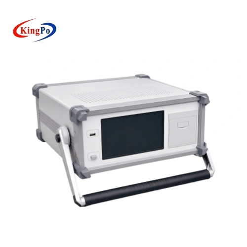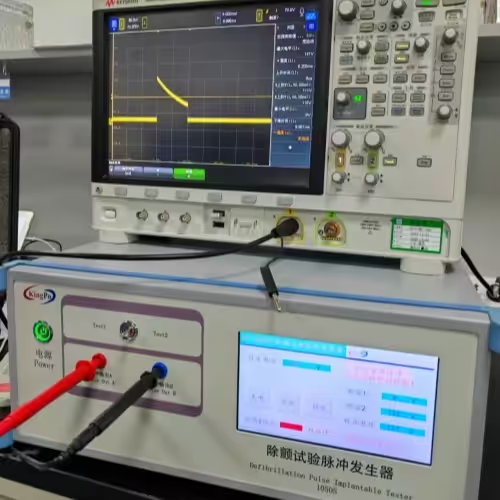
External defibrillators are performance-critical medical devices. For third-party laboratories, manufacturers and engineering teams, a defibrillator tester—also commonly called a defibrillator analyzer—must be able to capture delivered energy and waveform characteristics reliably under the required test conditions.
In practice, the measurement task extends beyond a single Joule reading. Depending on the applicable test procedure and device specification, the laboratory may need to evaluate delivered energy, biphasic waveform parameters, response under different load conditions, charge time and synchronized cardioversion timing while retaining traceable test records.
This guide explains the measurement principles, practical laboratory workflow and equipment-selection considerations for defibrillator output testing, with IEC 60601-2-4 as the primary standards context. It also explains how a defibrillator analyzer differs from defibrillation-proof test equipment used for ECG monitors, patient-connected medical equipment and active implantable devices.
Technical Overview
- Primary DUT: External cardiac defibrillator or AED
- Main measurements: Delivered energy, voltage/current waveform, load response, charge time and synchronization timing
- Primary standard context: IEC 60601-2-4
- Measurement direction: The DUT generates the shock; the analyzer receives and measures it
- Important distinction: A defibrillator analyzer is not the same as a defibrillation-proof tester or defibrillation test pulse generator
What Third-Party Labs Need Before Testing
A laboratory bench for external defibrillator output testing normally starts with a dedicated defibrillator tester or analyzer capable of safely receiving high-voltage, high-energy, non-sinusoidal pulses and reconstructing the parameters required by the test program.
Important analyzer characteristics may include:
- voltage and current measurement ranges suitable for the expected pulse amplitude;
- adequate analog bandwidth for rapid waveform transitions;
- sufficient sampling performance for the waveform being evaluated;
- stable, non-inductive test loads;
- delivered-energy calculation;
- waveform storage and parameter extraction;
- charge-time measurement;
- ECG simulation and synchronized cardioversion timing measurement where required;
- data storage or export for test records.
Some commercial defibrillator analyzers use sampling rates in the 250 kHz range or higher. This is a useful reference when comparing instruments, but sampling rate alone should not be treated as a universal acceptance requirement. Measurement suitability also depends on analog bandwidth, filtering, input range, load characteristics, waveform shape and the requirements of the applicable test procedure.
Before testing, the laboratory should confirm the DUT model and configuration, applicable standard edition, required operating modes, nominal energy settings, test loads, acceptance criteria and analyzer calibration status.
How a Defibrillator Tester Measures Delivered Energy
Delivered energy is determined by integrating instantaneous electrical power over the duration of the defibrillation pulse:
E = ∫ V(t) × I(t) dt
A defibrillator analyzer measures the voltage across the test load and the current flowing through it. The sampled voltage and current values are multiplied to determine instantaneous power and then numerically integrated over the shock duration to calculate energy in Joules.
Low measurement error depends on the complete measurement chain rather than on a single specification. Important factors include:
- adequate sampling performance;
- appropriate measurement bandwidth;
- characterized analog filtering;
- a low-inductance current path;
- stable load resistance;
- proper high-energy connections;
- documented analyzer calibration.
A 50 Ω non-inductive load is commonly encountered as a reference condition in defibrillator measurement systems. Additional load values may be used when the applicable procedure or DUT specification requires evaluation of output behavior under different simulated impedance conditions.
Practical Delivered-Energy Test Sequence
- Verify the analyzer model, serial number and calibration status. Complete any required warm-up or self-test.
- Configure the required non-inductive load and connect the defibrillator output using suitable high-energy adapters or paddle connections.
- Select the specified energy setting on the defibrillator.
- Initiate charging and wait for the defined ready condition.
- Discharge the defibrillator into the analyzer and capture the waveform together with the numerical measurements.
- Record delivered energy and any required peak-voltage, peak-current or timing parameters.
- Repeat the measurement at the required energy settings and load conditions defined by the test plan.
- Retain the waveform and test conditions with the final laboratory record.
If unexpected energy deviations appear at one load condition, the laboratory should check connections, load selection, DUT state and analyzer configuration before treating the result as a DUT failure.
Biphasic Waveform Capture and Analysis Without False Failures
Many contemporary external defibrillators use biphasic waveforms, including biphasic truncated exponential designs. In these systems, total delivered energy alone does not fully describe the output.
Depending on the test objective, waveform analysis may include:
- peak voltage for each phase;
- peak current for each phase;
- first-phase duration;
- second-phase duration;
- inter-phase interval;
- waveform decay or tilt;
- overall shock duration;
- residual voltage or offset where relevant;
- delivered energy.
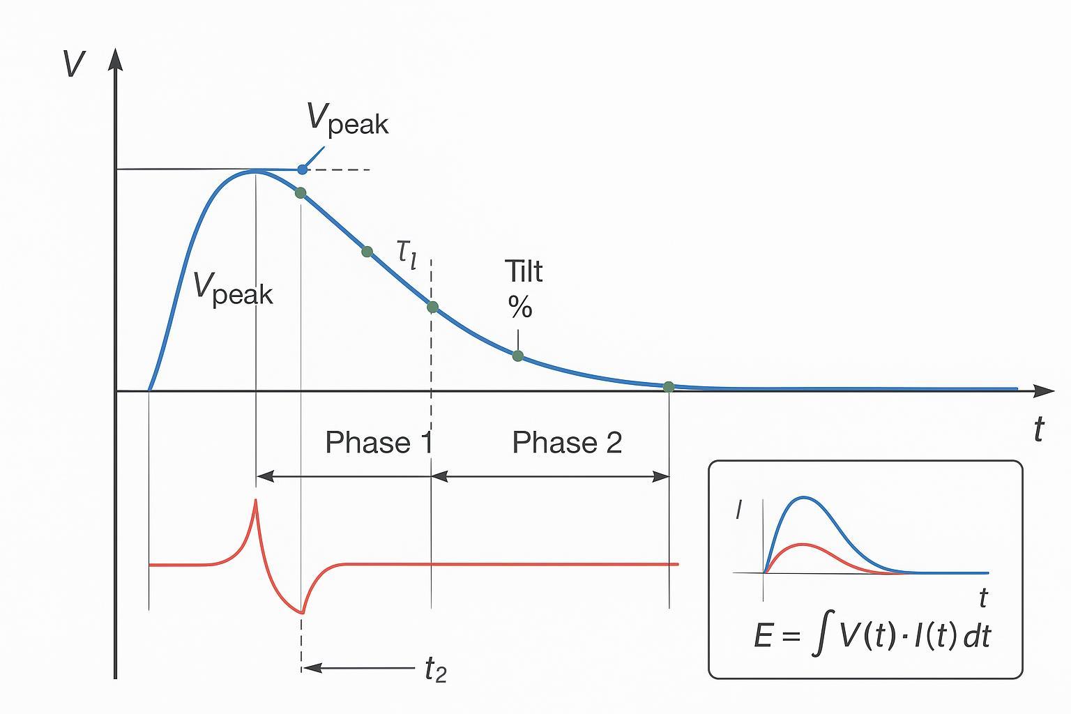
Waveform-related discrepancies do not automatically indicate a defective defibrillator. Insufficient analyzer bandwidth, inappropriate filtering, poor connection geometry, incorrect load selection or inadequate waveform acquisition can also distort measured peak values and phase transitions.
For this reason, laboratories should review both the stored waveform and the numerical result when a measurement falls close to an acceptance limit.
Load and Impedance Strategy in Defibrillator Testing
The electrical impedance presented to the defibrillator affects output voltage, current and potentially delivered energy. External defibrillators may also use impedance-dependent control strategies, making load selection an important part of performance evaluation.
A 50 Ω load is widely used as a reference condition in defibrillator analyzers and test procedures. For tests requiring evaluation across multiple impedance conditions, additional non-inductive loads may be used.
Examples commonly encountered in laboratory load systems include:
- 25 Ω;
- 50 Ω;
- 75 Ω;
- 100 Ω;
- 125 Ω;
- 150 Ω;
- 175 Ω;
- 200 Ω.
These values should be understood as examples of practical analyzer load configurations, not as a universal test sequence for every device. The actual load matrix should be selected according to the applicable requirement, DUT specification and approved laboratory procedure.
Additional high-impedance conditions may sometimes be evaluated during engineering characterization or robustness studies, provided the analyzer and load modules are designed for those conditions.
When reviewing results, laboratories should look for consistent energy and waveform behavior across the required loads. Abrupt or non-repeatable changes should trigger a check of the connection path and test setup before additional conclusions are drawn.
Charge Time and Synchronized Cardioversion Timing
Charge Time
Charge time describes the interval required for the defibrillator to reach the defined ready-to-discharge state at a specified energy setting and operating condition.
A practical sequence may include:
- selecting the specified energy;
- configuring the required test load;
- initiating the charge cycle;
- measuring the interval to the defined ready condition;
- delivering the shock;
- recording both timing and delivered-energy results.
Battery state, previous high-energy discharges, operating mode and environmental conditions may influence charging performance and should be controlled or recorded where required.
Synchronized Cardioversion Timing
In synchronized cardioversion mode, the defibrillator uses an ECG synchronization signal to determine when the shock is delivered. A suitable analyzer can provide the ECG reference signal and measure the timing relationship between that reference and the defibrillation pulse.
The test record may include:
- ECG rate;
- selected synchronization mode;
- energy setting;
- test load;
- measured synchronization delay;
- repeatability across the required conditions.
This timing measurement should be evaluated separately from delivered energy and waveform calculations.
IEC 60601-2-4 and IEC 62353: Different Test Contexts
IEC 60601-2-4 addresses the basic safety and essential performance of cardiac defibrillators. For design verification and conformity assessment of an external defibrillator or AED, the applicable edition of IEC 60601-2-4 and the manufacturer’s defined device configuration should be reviewed before the test sequence is established.
IEC 62353 has a different role. It addresses recurrent testing and testing after repair of medical electrical equipment. It should not be treated as an alternative version of IEC 60601-2-4 type testing.
| Test Context | Typical Evidence | Key Point |
|---|---|---|
| Delivered energy | Energy setting, measured Joules, load, DUT condition and analyzer identification | Evaluate using the applicable product test procedure |
| Waveform | Stored waveform, peak values, phase durations and required calculated parameters | Do not rely on energy value alone where waveform characteristics are required |
| Charge time | Energy setting, load, battery or operating condition and measured time | Test conditions must be defined and repeatable |
| Synchronization timing | ECG condition, synchronization mode and measured delay | Separate timing measurement from energy measurement |
| Recurrent / after-repair testing | Equipment identification, electrical safety results, functional checks and service records | IEC 62353 context differs from initial IEC 60601-2-4 conformity testing |
The analyzer specification alone does not establish compliance. The test method, DUT operating condition, required measurement points, acceptance criteria and reporting method must be determined from the applicable standard and laboratory procedure.
Data, Measurement Uncertainty and Audit-Ready Reporting
Traceability should be built into the test record rather than added after testing. For third-party laboratories and manufacturers maintaining controlled test systems, a useful record normally identifies both the DUT and the measurement equipment.
Depending on the test scope, records may include:
- DUT manufacturer, model and serial number;
- defibrillator operating mode;
- selected energy setting;
- selected load;
- measured delivered energy;
- peak voltage and current where required;
- phase durations and other waveform parameters;
- charge time;
- synchronized cardioversion timing;
- analyzer manufacturer, model and serial number;
- calibration certificate identification and date;
- operator and test date;
- test procedure reference;
- stored waveform or supporting data file;
- acceptance criteria and final result.
Measurement uncertainty becomes particularly important when a result is close to an acceptance limit or where the laboratory’s accredited scope and decision rule require uncertainty to be considered.
The uncertainty budget should reflect the actual measurement process. Depending on the parameter, relevant contributors may include analyzer calibration uncertainty, load tolerance, voltage and current measurement uncertainty, timing resolution, waveform acquisition and repeatability.
Selection Criteria for a Defibrillator Tester
When specifying or procuring a defibrillator tester, laboratories should compare the instrument against the intended test program rather than selecting solely from a headline energy range.
Energy Measurement Capability
Confirm the analyzer’s energy range, measurement accuracy and performance over the energy levels used by the DUT.
Voltage and Current Range
The measurement channels should accommodate the expected pulse amplitude without clipping while retaining suitable resolution at lower test levels.
Sampling and Analog Bandwidth
Sampling rate should be assessed together with analog bandwidth, filtering and waveform characteristics. A higher numerical sampling specification does not automatically guarantee a more accurate energy or waveform measurement.
Load Modules
Confirm that the analyzer supports the resistance values and energy levels required by the test procedure. Test loads should be suitable for high-energy pulse measurements and should minimize unwanted inductive effects.
Waveform Analysis
Depending on the test program, useful functions may include peak voltage, peak current, phase duration, inter-phase timing, waveform decay, stored waveform display and raw-data retention.
Charge-Time and Synchronization Measurement
Where these tests are required, confirm that the analyzer can reproduce the required ECG conditions and provide suitable timing measurement capability.
Data and Reporting
Laboratory users may require numerical export, waveform storage, report generation or integration with an existing data-management process. The required level of automation should be defined from the actual workflow rather than assumed to be necessary for every laboratory.
Calibration and Service
Review the analyzer’s calibration documentation, recommended calibration interval, service support and measurement traceability. For accredited testing, confirm that calibration evidence is suitable for the laboratory’s own quality-system requirements.
Example Workflow: Type Test to Production QA
For design verification or type testing, the test sequence should be based on the applicable standard, DUT specification and approved laboratory plan. A typical engineering workflow may combine several measurement tasks:
- baseline delivered-energy measurement under the specified reference load;
- waveform capture at the required energy settings;
- evaluation across additional impedance conditions where required;
- charge-time measurement;
- synchronized cardioversion timing checks where applicable;
- complete recordkeeping with analyzer identification and stored waveform data.
After design verification, a manufacturer may define a reduced production QA sequence based on the characteristics established during type testing. For example, production checks may use selected energy levels and a smaller set of load conditions rather than reproducing the entire engineering verification program on every unit.
Such a reduction should be justified by the manufacturer’s quality plan and product-validation data rather than by a generic test sequence.
Automation can reduce operator variability where test volume warrants it, but equipment identification, firmware or software configuration, calibration status and test-method revision should remain controlled.
For equipment returning from service or repair, the test context changes. Recurrent electrical safety and functional verification should follow the applicable service procedure and relevant recurrent-testing requirements rather than simply repeating the original type-test sequence.
Common Causes of Unexpected Defibrillator Test Results
Incorrect Load Selection
The selected test load directly affects pulse voltage and current. Confirm that both the nominal resistance and load configuration match the test procedure.
Poor High-Energy Connections
Loose, contaminated or inappropriate adapters can create inconsistent results and may affect measured peaks or energy calculations.
Insufficient Waveform Capture
A displayed energy value may appear stable even when waveform acquisition is inadequate. Review the waveform itself whenever peak values, phase duration or pulse shape are part of the evaluation.
Confusing Instrument Capability with Acceptance Criteria
The analyzer specification defines the measurement system’s capability. It does not define whether the DUT passes or fails. Acceptance criteria must come from the applicable standard, device specification or approved test procedure.
Using the Wrong Defibrillation Test Equipment
Not every device associated with a defibrillation pulse is tested using a defibrillator analyzer. The device under test must be identified before equipment is selected.
Defibrillator Analyzer vs Other Defibrillation Test Equipment
This distinction is particularly important when searching for “defibrillator test equipment,” because several very different medical-device tests involve similar high-voltage pulses.
| Device Under Test | What Happens During the Test? | Equipment Type |
|---|---|---|
| External defibrillator / AED | The DUT generates the shock. The test instrument measures energy, waveform and timing. | Defibrillator Tester / Analyzer |
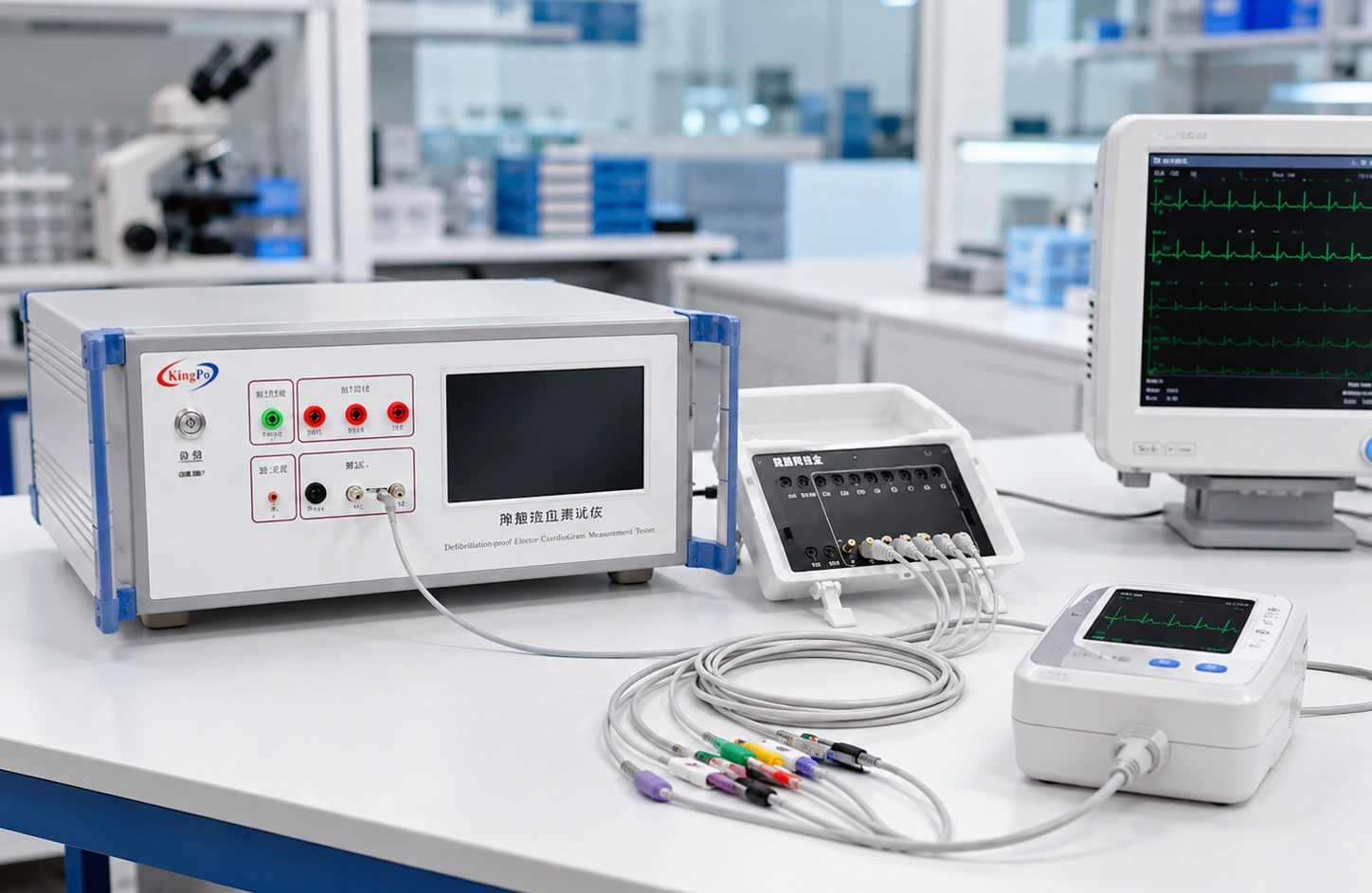
| ECG / patient monitor / patient-connected medical equipment | The test system applies a defined defibrillation-related pulse to the DUT to evaluate protection and energy reduction. | KP3301 Defibrillation-Proof and Energy Reduction Tester |
| Active implantable medical device | A defined defibrillation waveform is generated and applied for immunity or compatibility evaluation. | KP-1050S Defibrillation Test Pulse Generator |
| Defibrillation electrode / pad | The electrode itself is evaluated for electrical characteristics and performance associated with defibrillation exposure. | Defibrillation Electrode Performance Test Equipment |
If the main question is which type of defibrillation-related equipment is required for a specific DUT, see our Defibrillator Output Testing vs Defibrillation-Proof Testing guide.
Related KingPo Defibrillation Test Equipment
KP3301 Defibrillation-Proof and Energy Reduction Tester
The KP3301 is intended for defibrillation-proof and energy-reduction testing of patient-connected medical equipment. In this test direction, the test system generates the required test condition and applies it to the DUT.
It is not a clinical defibrillator analyzer used to measure the output of an AED or external defibrillator.
View KP3301 Technical Specifications →
KP-1050S Defibrillation Test Pulse Generator
The KP-1050S is used to generate defined defibrillation-related waveforms for active implantable medical device testing. Its function is fundamentally different from that of a defibrillator analyzer receiving and measuring the output of an external defibrillator.
View KP-1050S Technical Specifications →
Frequently Asked Questions
What is a defibrillator tester?
A defibrillator tester, commonly called a defibrillator analyzer, is a measurement instrument used to receive and evaluate the electrical pulse produced by an external defibrillator or AED. Typical measurements include delivered energy, waveform parameters, load response, charge time and synchronization timing.
How is defibrillator energy measured?
The analyzer measures voltage and current throughout the discharge and calculates delivered energy by integrating instantaneous electrical power over the pulse duration: E = ∫ V(t) × I(t) dt.
Why are different test loads used?
Load resistance affects defibrillator output voltage and current and may also affect energy-delivery behavior. Different load values may therefore be used when required by the applicable procedure or DUT specification.
Is a 50 Ω load always sufficient?
No. A 50 Ω non-inductive load is commonly used as a reference condition, but the complete load matrix depends on the applicable test requirement, DUT specification and laboratory procedure.
Is a 250 kHz sampling rate required by IEC 60601-2-4?
It should not be treated as a universal IEC 60601-2-4 requirement simply because some commercial analyzers use sampling rates around this level. Sampling performance must be considered together with bandwidth, filtering, waveform characteristics and the required measurement uncertainty.
What is the difference between IEC 60601-2-4 and IEC 62353?
IEC 60601-2-4 addresses the basic safety and essential performance of cardiac defibrillators. IEC 62353 addresses recurrent testing and testing after repair of medical electrical equipment. Their purposes and test scopes are different.
Can the KP3301 be used as a defibrillator analyzer?
No. The KP3301 is a defibrillation-proof and energy-reduction test system for patient-connected medical equipment. It applies a test condition to the DUT rather than measuring a shock produced by an external defibrillator.
Is the KP-1050S a defibrillator analyzer?
No. The KP-1050S is a defibrillation test pulse generator for defined medical-device immunity testing. Its role is to generate the required test waveform, not to measure the delivered energy of an AED or external defibrillator.
What information should be prepared before selecting defibrillation test equipment?
First identify the DUT: external defibrillator, ECG or patient monitor, defibrillation electrode, or active implantable medical device. Then confirm the applicable standard, required test items, pulse or energy conditions, load requirements and reporting needs. Identifying the DUT correctly usually determines the correct equipment category.
Conclusion
A defibrillator tester should be evaluated as a complete measurement system rather than by delivered-energy range alone. Reliable testing depends on the interaction between voltage and current measurement, waveform acquisition, non-inductive loads, timing capability, calibration and a clearly defined laboratory procedure.
For external defibrillators and AEDs, the DUT generates the high-energy pulse and the defibrillator analyzer measures its output. For other medical-device tests involving defibrillation pulses, the test direction may be completely different.
Where the DUT is an ECG monitor or other patient-connected medical device, see the KP3301 Defibrillation-Proof and Energy Reduction Tester. For active implantable medical device defibrillation immunity testing, see the KP-1050S Defibrillation Test Pulse Generator.