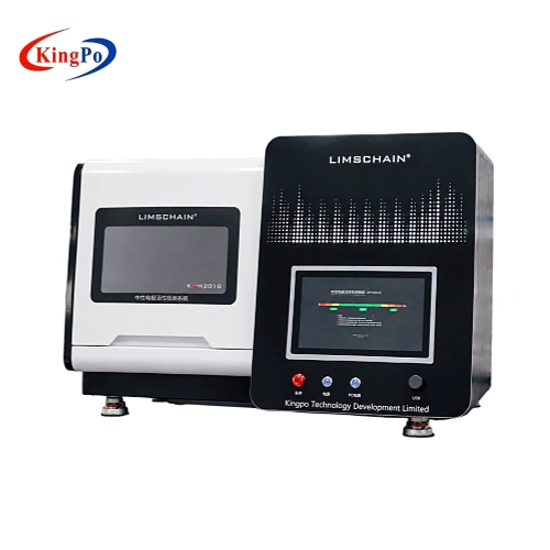
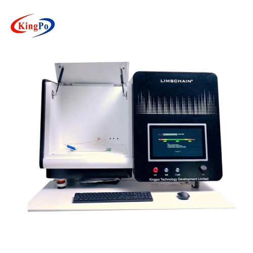
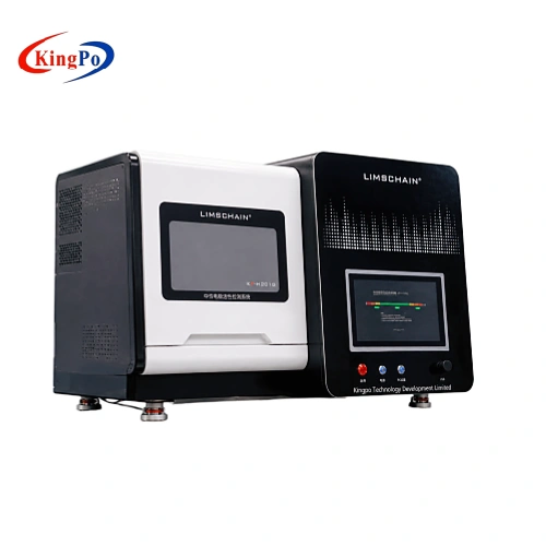
Product Overview
A neutral electrode, also commonly called a patient return electrode, provides the return path for high-frequency current during monopolar electrosurgery. An important part of its safety evaluation is determining whether the current is distributed over the electrode contact area without creating excessive localized heating.
The ZLR-320 is built specifically around this thermal-performance problem.
Instead of providing only a single temperature reading, the system uses a multi-point temperature measurement surface to determine how temperature is distributed beneath and around the neutral electrode. This allows the laboratory to identify localized hotspots that may not be visible from an average temperature value.
For conventional neutral electrodes, IEC 60601-2-2 Clause 201.15.101.5 evaluates the maximum temperature rise over a defined local area following application of the specified HF test current. The ZLR-320 combines the HF current source, test surface, temperature measurement array, CQM-related simulation functions and software interface into one laboratory system.
This makes the equipment particularly useful where repeatability, temperature distribution and documented test conditions are more important than simply determining whether the electrode becomes warm.
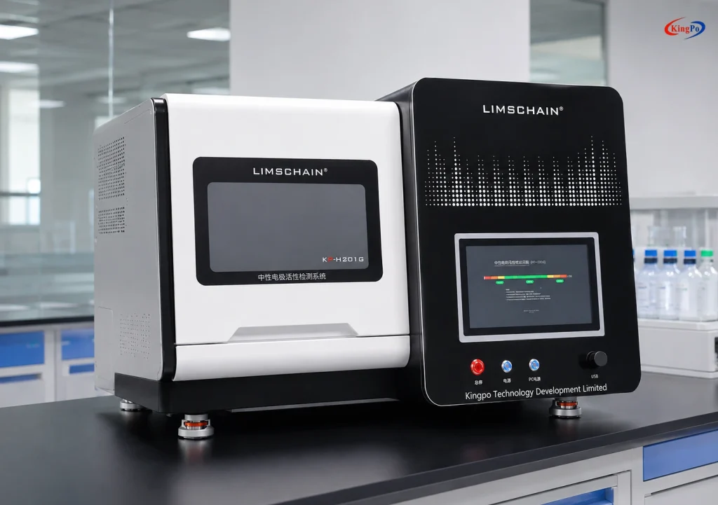
Technical Specifications
| Parameter | Specification |
|---|---|
| Applicable Standard | IEC 60601-2-2:2017, Clause 201.15.101.5 |
| Related Standard | GB 9706.202-2021 |
| Temperature Measurement Area | 12 cm × 22 cm, gold-plated test area |
| Spatial Resolution | 1 cm² |
| Temperature Sensors | 416 sensors, 16 × 26 array |
| Conventional HF Test Current | 350 mA / 500 mA / 700 mA RMS |
| Standard Test Duration | 60 s |
| Configurable Test Duration | 10 s to 300 s |
| Temperature Measurement Time | <1 s |
| Temperature Measurement Accuracy | ±0.4 °C |
| Simulated Test-Medium Thickness | 5 mm / 10 mm / 15 mm / 20 mm |
| CQM Simulation Range | 2 Ω to 100 Ω |
| CQM Measurement Accuracy | ±(3% + 3 Ω) |
| Relative CQM Impedance Change | 0% to 160% |
| CQM Alarm Region | 130% to 140% relative increase |
| Equipment Dimensions | 1040 × 640 × 640 mm |
| Total Weight | Approx. 66 kg, including main unit, measuring table and cables |
| Power Supply | 220 V AC, 50 Hz |
| Recommended Test Environment | 23 ± 2 °C initial electrode and test-surface temperature |
| Storage Environment | 0 to 50 °C, 10% to 90% RH |
| Operating System | Windows 10 embedded computer |
| Interface Language | Chinese / English |
| Data Integration | API available for integration with LIMS or other laboratory systems |
KINGPO’s available technical specification also lists a 1.5 A high-current mode. Because high-current-mode evaluation is different from the conventional 350 / 500 / 700 mA test-current conditions of Clause 201.15.101.5, the required standard edition, HF surgical equipment application and neutral electrode specification should be reviewed before this function is included in a project configuration.
What Does the ZLR-320 Actually Measure?
The primary purpose of the ZLR-320 is not to test the output performance of an electrosurgical generator.
It evaluates the thermal behaviour of the neutral electrode itself.
During monopolar HF surgery, current passing through the return electrode should be distributed over a sufficiently large contact area. If current becomes concentrated in a smaller region because of electrode geometry, contact conditions or other factors, localized heating can increase.
The test therefore focuses on questions such as:
- How much does the contact surface temperature increase during the specified HF current application?
- Is the heating distributed evenly across the electrode?
- Is there a localized hotspot within a small part of the contact area?
- How does the electrode perform under the test-current condition associated with its intended patient weight range?
- How does the thermal behaviour change when the effective electrode contact area or test condition changes?
The temperature map provides substantially more useful engineering information than a single-point temperature measurement because it shows where the highest temperature rise occurs.
IEC 60601-2-2 Clause 201.15.101.5 Test Principle
For conventional neutral electrodes, IEC 60601-2-2 Clause 201.15.101.5 is intended to address the risk of thermal injury at the neutral-electrode application site.
Under the standard test method, different HF test currents are associated with the marked patient weight range:
| Patient Weight Range | Conventional Test Current |
|---|---|
| <5 kg | 350 mA RMS |
| 5 kg to 15 kg | 500 mA RMS |
| >15 kg or unspecified | 700 mA RMS |
The general test sequence can be understood in four stages.
1. Establish the Initial Thermal Condition
The neutral electrode and test surface are brought to the required initial thermal condition. For a surrogate medium or test device, IEC 60601-2-2 specifies an initial temperature of 23 ± 2 °C.
A reference temperature map is obtained before HF current is applied.
2. Apply the Neutral Electrode
The electrode under test is applied to the test surface according to the applicable test procedure and electrode instructions.
For a monitoring neutral electrode, the effective contact area and CQM-related conditions can be relevant to the test configuration.
3. Apply the HF Test Current
For the conventional test, an approximately sinusoidal HF test current is applied and maintained for the specified test period.
The principal test currents are:
- 350 mA for the <5 kg patient range
- 500 mA for the 5 kg to 15 kg range
- 700 mA for the >15 kg or unspecified range
The standard test duration is 60 seconds.
4. Map the Temperature Rise
After HF current application, a second temperature scan is compared with the reference scan.
For the conventional-neutral-electrode test in Clause 201.15.101.5, the maximum temperature rise over any defined 1 cm² local area is evaluated against the applicable requirement.
The ZLR-320 uses a 416-point temperature sensor array with 1 cm² spatial resolution, a stated temperature measurement accuracy of ±0.4 °C, and a complete measurement time of less than one second.
Why High-Resolution Temperature Mapping Matters
Neutral electrode thermal performance cannot be judged reliably from average temperature alone.
Consider two electrodes that show the same average temperature increase. One may distribute the HF current uniformly, while the other may contain a small area with significantly higher heating. From a patient-contact perspective, those two results are not equivalent.
For this reason, the ZLR-320 measures the temperature distribution across the contact area rather than relying on a single temperature sensor.
Its 16 × 26 sensor array provides 416 measurement points, allowing the laboratory to identify:
- Localized thermal hotspots
- Uneven heat distribution
- Changes associated with different electrode designs
- Effects of reduced effective contact area
- Repeatability between multiple electrode samples
This is particularly useful during product development because it shows not only whether a test result meets the applicable limit, but also how the electrode is behaving thermally.
Use of a Surrogate/Test Device Instead of Human Subjects
IEC 60601-2-2 allows suitable electrically and thermally equivalent surrogate media or test devices to be used within the Clause 201.15.101.5 test methodology.
However, this should not be interpreted as meaning that any artificial test surface automatically produces results equivalent to human testing.
Where a surrogate medium or test device is used for formal compliance testing, the standard requires documented evidence supporting its relationship to the human-subject test protocol.
The ZLR-320 provides the controlled hardware platform required for repeatable surrogate/test-device testing, including HF current application, defined test-surface conditions, temperature mapping and CQM-related functions.
For certification or accredited laboratory work, users should confirm that the test-device qualification evidence, laboratory procedure and applicable standard edition are acceptable for the intended conformity-assessment program before testing.
This distinction is important: the equipment improves repeatability and reduces dependence on direct human-subject testing, but the validity of a surrogate methodology must still be supported by the documentation required for the applicable compliance program.
Suitable Neutral Electrode Types
According to the current ZLR-320 technical documentation, the system is intended primarily for:
- Self-adhesive neutral electrodes
- Disposable neutral electrodes
- Conventional patient return electrodes used with HF surgical equipment
- Monitoring neutral electrodes where the required CQM-related test conditions can be established
The current technical specification states that the standard configuration is not intended for rubber neutral electrodes or capacitive neutral electrodes.
If your electrode differs from a conventional disposable adhesive return electrode, provide the sample specification and intended clinical application before quotation.
This is particularly important for:
- Capacitive neutral electrodes
- Reusable rubber electrodes
- Electrodes intended for high-current surgical modes
- Unusual electrode geometries
- Proprietary CQM electrode structures
CQM Simulation and Contact-Area Evaluation
Monitoring neutral electrodes are used together with a Contact Quality Monitor (CQM) to detect changes associated with electrode-to-patient contact.
The ZLR-320 includes a CQM simulation function with:
- 2 Ω to 100 Ω simulation / measurement range
- ±(3% + 3 Ω) stated measurement accuracy
- 0% to 160% relative impedance-change range
- Configurable monitoring around the stated 130% to 140% alarm region
This function is useful when establishing the required test condition and effective contact area for thermal-performance evaluation of monitoring electrodes.
It should not, however, be confused with the separate neutral electrode contact impedance test of IEC 60601-2-2 Clause 201.15.101.6.
Temperature Rise Testing vs. Contact Impedance Testing
IEC 60601-2-2 treats neutral-electrode thermal performance and contact impedance as different evaluations.
| Test Requirement | ZLR-320 Temperature Rise Tester | Neutral Electrode Contact Impedance Tester |
|---|---|---|
| Main Clause | 201.15.101.5 | 201.15.101.6 |
| Main Purpose | Evaluate thermal performance | Evaluate electrode electrical contact impedance / capacitance |
| Main Test Quantity | Local temperature rise | Impedance / capacitance |
| Test Method | HF current + temperature mapping | HF voltage / current measurement |
| Main Concern | Localized heating at the NE site | Excessive ohmic heating caused by poor electrical contact |
A laboratory working on comprehensive neutral-electrode evaluation may therefore require both test functions, depending on the product and applicable compliance program.
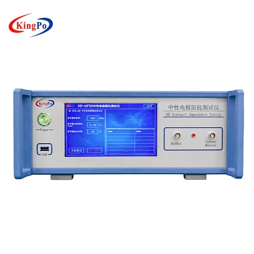
For dedicated Clause 201.15.101.6 testing, see the KINGPO Neutral Electrode Contact Impedance Tester.
Typical Laboratory Applications
Neutral Electrode Product Development
R&D engineers can use the temperature map to compare electrode constructions, conductive-area designs, adhesive structures and other design variables.
Instead of obtaining only a pass/fail result, engineers can see how changes influence the location and magnitude of thermal hotspots.
IEC 60601-2-2 Verification Testing
Medical device manufacturers and laboratories can use the system when establishing a controlled test setup for neutral-electrode thermal-performance evaluation associated with Clause 201.15.101.5.
Sample-to-Sample Comparison
The controlled test platform helps laboratories compare multiple electrode samples under consistent current, duration and temperature conditions.
This is useful for design verification, supplier evaluation and engineering investigation of abnormal test results.
Third-Party and Certification Laboratory Testing
Testing organizations can use the equipment as part of a documented IEC 60601-2-2 neutral-electrode test setup where repeatable HF current application, temperature mapping and recorded test conditions are required.
The applicable surrogate/test-device validation evidence should be confirmed as part of the laboratory’s compliance procedure.
Quality and Failure Analysis
If an electrode shows an unexpected temperature rise, the multi-point temperature map can help determine whether the problem is localized or distributed across the electrode contact area.
This information can support further investigation into electrode construction, contact area, material consistency or sample preparation.
Software and Laboratory Integration
The ZLR-320 incorporates an embedded computer running Windows 10 and provides a Chinese / English user interface.
The system is designed to allow test conditions and measurement results to be managed from a dedicated interface rather than requiring multiple separate instruments for routine operation.
An API interface is available for integration with LIMS or other laboratory data-management systems, subject to the selected software configuration.
For laboratories that require automated report generation, data export or communication with an existing test platform, the required interface and data format should be confirmed before ordering.