IEC 60601-1 testing is often described as a final verification activity: the product is completed, samples are sent to a laboratory, and the laboratory determines whether the equipment complies.
In practice, the most difficult IEC 60601-1 issues are rarely created in the laboratory.

They usually originate much earlier — in decisions about the power architecture, insulation system, patient connections, accessories, operating modes and risk controls. Formal testing simply exposes whether those decisions were defined well enough.
For that reason, a useful pre-compliance review should not attempt to reproduce every test in IEC 60601-1. Its purpose is to establish whether the medical electrical equipment has a coherent safety architecture and whether that architecture can be translated into a defensible test configuration.
The Test Program Starts With the Product Definition
Before individual electrical tests are considered, the applicable IEC 60601 framework has to be established.
IEC 60601-1 provides the general requirements for basic safety and essential performance, but it is rarely the only document relevant to a medical electrical product. Depending on the intended use and equipment type, collateral standards and particular standards may add, modify or replace requirements in the general standard.
This has a practical consequence during pre-compliance.
That distinction should be resolved before a detailed test plan is prepared.
A home-use product, an electrosurgical generator, an ECG monitor and a defibrillator may all fall within the IEC 60601 family, but they do not present the same hazards and they should not enter the laboratory with the same test assumptions.
The Insulation Architecture Should Be Understandable Before Testing Begins
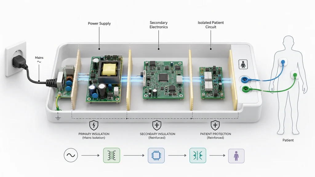
For electrically powered medical equipment, one of the most useful pre-compliance exercises is to trace the protection path through the product.
Consider a simplified patient-connected system:
The block diagram appears straightforward, but the safety assessment depends on details that are not visible from the block diagram alone.
Which barrier provides protection from mains?
Is that protection intended for an operator, a patient, or both?
Does a second isolation barrier exist between the secondary circuit and the patient circuit?
What happens when a USB, Ethernet, programming or other external interface is connected?
These questions are better answered with an insulation diagram than with a collection of component certificates.
A useful insulation review should identify, for each relevant barrier:
- working voltage;
- required Means of Protection;
- insulation type;
- components forming the barrier;
- creepage and clearance paths;
- dielectric-strength considerations.
This is also where a common assumption needs to be challenged.
A medically certified power supply does not certify the complete medical device
Using an IEC 60601-qualified AC/DC power supply can simplify the design, but the certificate applies to that component under defined conditions.
The end product still needs to demonstrate an adequate protection path through the complete system.
External interfaces, secondary circuitry, patient circuits, grounding and the way the power supply is integrated can all affect that assessment.
In other words, the certificate is evidence for one part of the safety architecture. It is not the safety architecture itself.
Patient Connections Need to Be Defined Electrically, Not Just Physically
Applied Part classification is another area where apparently simple product descriptions can become ambiguous during testing.
Statements such as:
are not usually enough to define the test configuration.
The engineer needs to identify the actual Applied Part, its patient connections and the electrical relationship between those connections and the rest of the equipment.
For example, a patient monitor may include electrodes, sensors, communication interfaces and accessory connectors. Some of those are patient connections; some are not. Several patient connections may form one Applied Part, while another function may require a different classification.
Before leakage-current testing begins, it should therefore be possible to answer:
- Which parts of the equipment are Applied Parts?
- Which patient connections belong to each Applied Part?
- Is the classification B, BF or CF?
- Are the patient connections electrically common or isolated from one another?
- Can an accessory alter the intended isolation?
If those answers are unclear, the leakage-current test configuration is also unclear.
Leakage Current Is Better Treated as a Circuit Problem Than an Analyzer Function
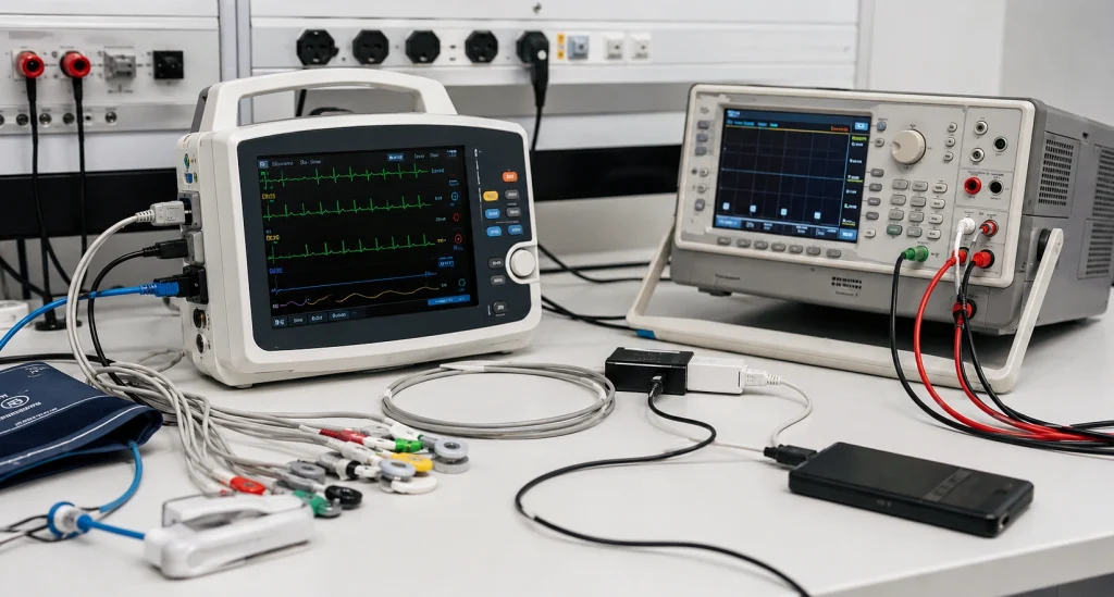
Leakage-current testing is sometimes approached as a sequence of instrument settings.
Select the measurement.
Reverse polarity.
Open protective earth.
Record the result.
That process is necessary, but it does not replace understanding the current path.
A more useful pre-compliance review starts with the circuit:
The answer may change when the product configuration changes.
A device might produce an acceptable patient leakage current when tested as a standalone unit and a different result when connected to:
- a mains-powered computer;
- an external monitor;
- a charger;
- another medical device;
- a communication interface;
- an accessory with an earth connection.
This is particularly important for systems that appear electrically floating until an external interface is connected.
The pre-compliance test should therefore reproduce the intended system configuration rather than an artificially simplified configuration that is easier to pass.
A leakage-current record should also describe the condition under which the result was obtained.
Instead of recording only:
a technically useful record would identify the important configuration:
That result can be reviewed, reproduced and compared with subsequent design revisions.
Single Fault Conditions Should Follow the Safety Architecture
IEC 60601-1 does not evaluate equipment only while everything is functioning normally.
The equipment must also remain safe under relevant Single Fault Conditions.
This is another reason why a generic pre-test checklist is of limited value.
The relevant faults depend on what the design relies upon for protection.
For one product, interruption of protective earth may be important.
For another, the critical issue may be failure of:
- an insulation component;
- a temperature-control device;
- a cooling system;
- a safety relay;
- a component used as part of a Means of Protection.
The engineering question should therefore be:
This connects the electrical design directly to the risk-management process.
If the team cannot identify which components or construction features are relied upon to control a particular electrical or thermal hazard, formal fault testing is likely to uncover questions that should have been resolved during design review.
There Is No Single “Worst-Case Configuration”
Manufacturers are often asked to supply the equipment in its worst-case operating condition.
That wording can be misleading.
The configuration producing the highest temperature may not produce the highest leakage current.
The condition most demanding for the power supply may not be the configuration relevant to dielectric-strength testing.
For example:
A more defensible approach is therefore to establish the worst-case configuration for each test or hazard, rather than trying to define one universal product state for the complete IEC 60601 evaluation.
This is a small distinction, but it can substantially improve a test plan.
Accessories Are Part of the Electrical Configuration
Another source of avoidable rework is sending the main unit to the laboratory before the final accessory configuration has been established.
For patient-connected equipment, the intended system may also include:
- electrodes;
- patient cables;
- sensors;
- probes;
- foot switches;
- chargers;
- communication cables;
- external displays;
- power adapters.
These items are not always electrically neutral.
A cable can change capacitance.
An external supply can change the isolation architecture.
A communications connection can introduce an earth path.
A patient accessory can change how patient connections are grouped during leakage-current measurements.
For this reason, the sample configuration submitted for testing should represent the product configuration that is actually intended to be placed on the market.
Construction Review Should Come Before Destructive or High-Stress Testing
Pre-compliance is often associated immediately with hipot and leakage-current measurements.
A construction review should normally come first.
Before high-voltage testing, it is worth examining the physical implementation of the protection system:
- mains-to-secondary PCB spacing;
- creepage and clearance around isolation components;
- slots used to increase creepage;
- transformer construction;
- optocoupler and DC/DC isolation;
- mains wiring segregation;
- insulation sleeves;
- enclosure openings;
- accessible metal parts;
- protective-earth bonding.
This review is important because different requirements verify different characteristics.
Passing a dielectric-strength test does not establish that required creepage and clearance distances are present.
Likewise, compliant spacing does not eliminate the need for dielectric-strength verification.
The protection system has to satisfy both construction requirements and applicable tests.
Protective Earth Is Also a Mechanical Design Issue
Class I equipment illustrates this particularly well.
On the schematic, protective earth may be represented by a single clean connection.
The actual resistance path may include:
Problems can therefore appear in places that do not exist on the electrical schematic.
Paint beneath an earth lug, anodized surfaces, loose bonding hardware or reliance on a hinge for electrical continuity can all affect the final PE path.
A meaningful pre-compliance measurement should therefore use the finished mechanical arrangement.
Testing from an ideal bare-metal chassis point may produce an excellent result while bypassing the exact connection that the production equipment relies upon for protection.
Essential Performance Needs an Observable Criterion
Essential Performance becomes difficult to evaluate when it is expressed only as a general statement such as:
For testing purposes, the required function needs to be observable and measurable.
The manufacturer should know:
- which function is considered Essential Performance;
- what degradation could result in unacceptable risk;
- what parameter will be monitored;
- what range is acceptable;
- what constitutes failure;
- whether temporary degradation or recovery is permitted.
This becomes especially important when IEC 60601-1 is combined with EMC or a particular standard.
The laboratory can expose the device to a defined disturbance, fault or operating condition, but the manufacturer must still establish what constitutes acceptable clinical or safety-related performance.
What Is Worth Pre-Testing Before Formal Submission?

A pre-compliance program does not need to reproduce an entire accredited IEC 60601 evaluation.
Its value is highest when it targets measurements that can expose weaknesses in the product architecture while design changes are still possible.
For many electrically powered medical devices, useful early checks include:
| Review / Measurement | What It Can Reveal |
|---|---|
| Insulation and construction review | Incorrect MOOP/MOPP assumptions, insufficient spacing, isolation bypasses |
| Protective-earth continuity | Weak mechanical bonding or excessive resistance in the PE path |
| Leakage-current measurements | Unexpected current paths through patient, enclosure or external interfaces |
| Dielectric-strength checks | Weakness in defined insulation barriers |
| Temperature measurements | Components or surfaces approaching unacceptable temperatures |
| Fault-condition trials | Dependence on a single component or protection measure |
| Accessory/configuration review | Differences between the test sample and intended-use system |
The objective is not to generate a certification report.
It is to find problems while the cost of changing the product is still relatively low.
Information That Should Be Stable Before the Sample Leaves
A product is much easier to evaluate when the technical documentation and the physical sample describe the same design.
Before formal submission, the following information should normally be reasonably mature:
The general, collateral and particular standards used as the compliance basis.
Including protection class and Applied Part classification.
Showing the Means of Protection between mains, accessible circuitry and patient connections.
Including the components relied upon for electrical, thermal or mechanical safety.
Including the conditions selected for temperature, leakage, fault and performance testing.
Defining what is included in the evaluated system.
With measurable pass/fail conditions where applicable.
Showing how identified hazards and risk-control measures relate to the design and verification activities.
None of these documents needs to make the laboratory’s evaluation unnecessary.
They need to make the product understandable.
A Practical Readiness Test
There is a useful distinction between a product that is physically complete and one that is ready for IEC 60601 testing.
Before releasing the sample, the engineering team should be able to explain, without reconstructing the design during the discussion:
Where are the Means of Protection?
What exactly constitutes each Applied Part?
Which connections can alter the leakage-current path?
Which fault removes one layer of safety protection?
Which operating condition is worst case for each major test?
What measurable function represents Essential Performance?
If these questions already have clear answers, the laboratory can concentrate on verification.
If they do not, formal testing is likely to become part verification and part design investigation.
That distinction is often where unnecessary test cycles begin.
Conclusion
IEC 60601-1 pre-compliance is most effective when it is treated as an engineering review rather than a shortened certification program.
The purpose is not to perform every clause before the laboratory does.
It is to establish that the medical electrical equipment has a clearly defined safety architecture, that the intended-use configuration has been identified, and that the manufacturer understands how the product is expected to behave when one layer of protection is challenged.
By the time the formal test sample is submitted, the laboratory should be verifying those assumptions — not discovering them for the first time.