
An ECG monitor may operate from a 12 VDC supply and measure patient signals at only the millivolt level. So a reasonable engineering question is:
Because the high voltage is not necessarily generated by the ECG. It can enter the ECG through the patient connections during defibrillation. That distinction is the key to understanding defibrillation-proof testing.
The Risk Does Not Come From the 12 V Supply
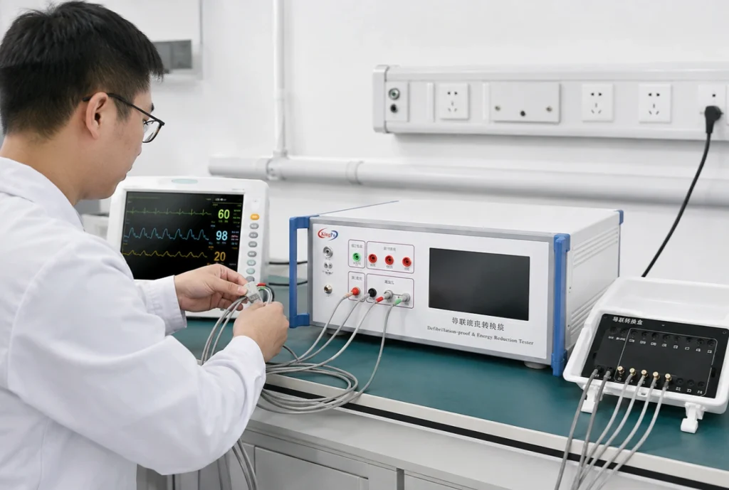
During normal operation, ECG electrodes measure very small physiological signals.
But consider a clinical situation in which a patient remains connected to an ECG monitor while an external defibrillator is used.
The electrical path can become:
Defibrillator
→Patient
→ECG Electrodes
→ECG Input Circuit
The ECG is now exposed to an external transient that has little to do with its normal operating voltage.
So the relevant question is not:
It is:
This is why a low-voltage power supply alone cannot determine whether defibrillation-related testing is required.
Defibrillation-Proof Does Not Just Mean “The PCB Survived”
A common misunderstanding is that the test simply checks whether the ECG still powers on after a high-voltage pulse.
The evaluation can be broader.
Depending on the equipment type and applicable standard, the laboratory may need to consider whether:
- the patient-connected circuit withstands the specified stress;
- excessive energy is transferred through the equipment;
- hazardous residual voltages are produced;
- the protection circuit remains safe;
- the ECG channel recovers appropriately after the event.
So a device that is not visibly damaged has not automatically demonstrated full compliance. The test is about the behaviour of the complete patient-connected protection system.
Why the ECG Leads Matter
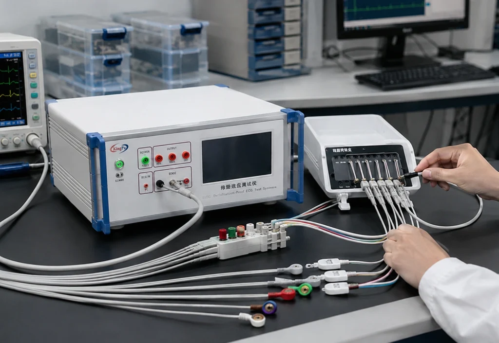
ECG equipment can have several patient connections, such as limb leads and chest leads.
The test therefore cannot be reduced to:
The laboratory must identify the required test arrangement from the applicable standard.
Depending on the test, this can involve different patient-lead groupings and different electrical paths.
Two important concepts are common-mode and differential-mode testing.
Common-Mode
Multiple patient connections may be stressed together relative to another reference point.
Differential-Mode
The stress is applied between selected patient connections or lead groups.
These arrangements challenge the ECG input protection in different ways.
That is why the laboratory needs to know which connections, how they are grouped, relative to what reference point, and under which test network.
Why Positive and Negative Polarity Are Both Important
ECG input protection circuits are not always electrically symmetrical.
They may contain:
- current-limiting resistors;
- protection diodes;
- transient suppressors;
- RC networks;
- isolation components;
- analogue front-end protection.
A positive transient and a negative transient can therefore follow different current paths.
Passing one polarity does not automatically prove equivalent behaviour under the opposite polarity.
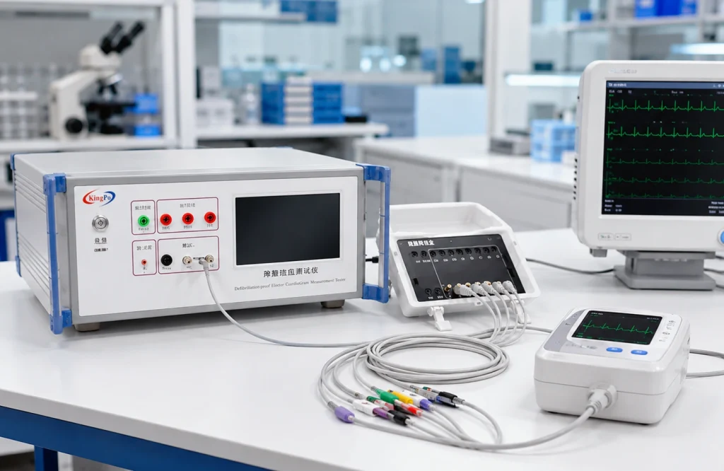
For this type of evaluation, the KingPo KP3301 Defibrillation-Proof and Energy Reduction Tester supports controlled positive and negative charging voltages up to ±5.5 kV, together with common-mode and differential-mode test configurations.
Why a 5 kV Hipot Tester Is Not the Same Thing
Another common question is:
Usually, these are different tests.
A hipot tester primarily evaluates insulation under a specified high-voltage condition.
A defibrillation-related test reproduces a defined transient through a particular electrical network and patient-connection arrangement.
The test condition can depend on factors such as:
Capacitance
Resistance
Inductance
Polarity
Discharge Behaviour
Lead Configuration
Delivered Energy
The voltage may look similar, but the electrical stress is not necessarily the same.
Energy Reduction Is Another Part of the Problem
Voltage withstand is not the only consideration.
A circuit might survive the transient while still allowing an unacceptable amount of energy to pass through a particular path.
This is why defibrillation-related testing may also involve energy-reduction evaluation.
The KP3301 includes an energy-reduction test function in addition to defibrillation-proof testing.
This is an important reminder that the peak voltage alone does not fully describe the event. The test network and delivered energy matter as well.
Does Every 12 V Medical Device Need This Test?
No.
A 12 V supply does not automatically mean that defibrillation-proof testing is required.
But it also does not justify the opposite conclusion:
The requirement depends on factors such as:
- medical device type;
- intended clinical use;
- applied part;
- patient-connected circuit;
- applicable IEC 60601 particular standard;
- specific clause and test configuration.
Diagnostic ECG equipment, ECG monitors and multifunction patient monitors are examples where these requirements need to be reviewed carefully.
The correct sequence is:
DUT
→
Intended Use
→
Applied Part
→
Applicable Standard
→
Clause
→
Test Circuit
not:
12 V Supply
→
No High-Voltage Test
What Should Be Confirmed Before Testing?
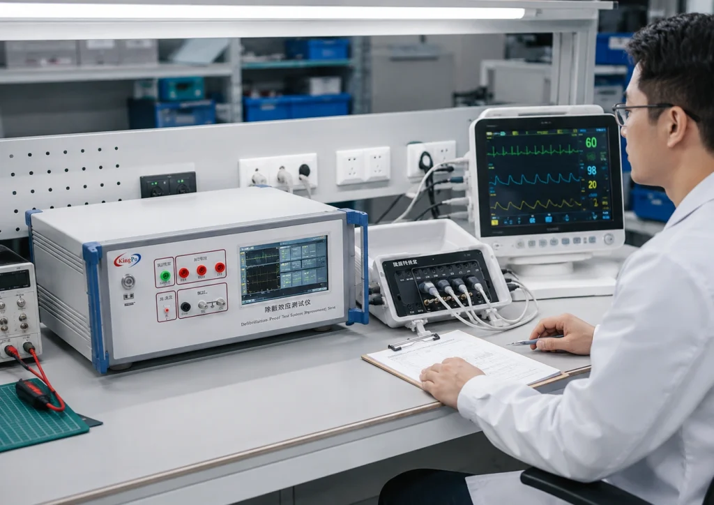
Before configuring a defibrillation-proof test system, the laboratory should confirm:
- medical device type;
- applicable standard and edition;
- applied-part classification;
- number and type of patient leads.
- common-mode or differential-mode requirement;
- positive and negative polarity requirements;
- energy-reduction requirement;
- required post-test performance or recovery checks.
For laboratories building a broader medical electrical safety capability, these requirements should also be reviewed together with the applicable IEC 60601-1 test equipment rather than selecting equipment from voltage range alone.
Engineering Takeaway
When an engineer asks:
“Our ECG runs on only 12 V. Why are we testing it with several kilovolts?”
the answer is simple:
Because the high voltage can come from an external defibrillator through the patient connections—not from the ECG’s 12 V power supply.
That is why defibrillation-proof testing starts with the clinical use scenario and patient-connected circuit, not just the internal supply voltage.
Before testing, confirm the device type, applied part, applicable particular standard, patient-lead configuration and exact test circuit.
Only then can the laboratory determine what defibrillation-related test is actually required.
