1000 Hz as Reference Signal
According to ITU-R 468-4 (Measurement of audio noise levels in sound broadcasting), the frequency response at 1000 Hz is 0 dB (see image below), making it suitable as a reference level signal for evaluating the frequency response performance of audio amplifiers.

Peak Response Frequency Signal
If the manufacturer declares that the audio amplifier is not intended to operate at 1000 Hz, the audio signal source frequency should be changed to the peak response frequency. The peak response frequency is the signal source frequency at which the maximum output power is measured across the rated load impedance (hereinafter referred to as the speaker) within the intended operating range of the audio amplifier. In practice, the tester can fix the signal source amplitude and sweep the frequency, then check the signal source frequency corresponding to the maximum RMS voltage appearing across the speaker—this is the peak response frequency.
Output Power Types and Adjustment — Maximum Output Power
The maximum output power is the maximum power that can be delivered to the speaker, corresponding to the maximum RMS voltage. Common audio amplifiers often use OTL or OCL circuits based on Class AB amplifier principles. When a 1000 Hz sine wave audio signal is input to the audio amplifier and it enters the saturation region from the amplification region, the signal amplitude can no longer increase, the peak voltage is limited, and flat-top distortion appears at the waveform peaks.
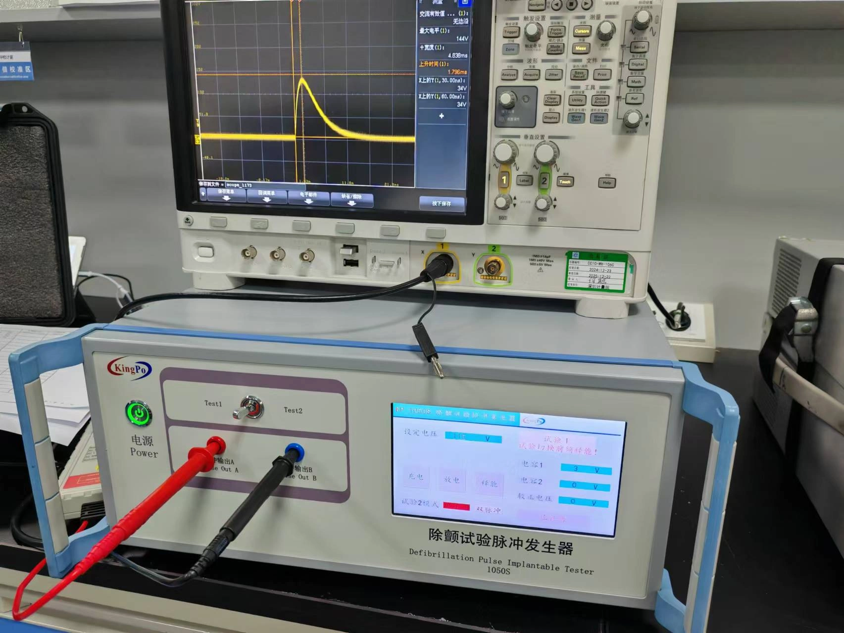
By using an oscilloscope to monitor the output waveform across the speaker, it can be observed that when the signal amplitude can no longer increase in RMS value, peak distortion occurs (see Figure 2). At this point, it is considered to have reached the maximum output power state. When peak distortion appears, the crest factor of the output waveform falls below the sine wave crest factor of 1.414 (as shown in Figure 2, crest factor = peak voltage / RMS voltage = 8.00 / 5.82 ≈ 1.375 < 1.414).

Output Power Types and Adjustment — Non-Clipping Output Power
Non-clipping output power is the output power achieved by reducing the gain (backing off the signal) to the boundary between the saturation and amplification regions while the speaker is operating at maximum output power with peak distortion present (operating point biased toward the amplification region). The audio output waveform presents a complete 1000 Hz sine wave with no peak distortion or clipping, and its RMS voltage is also lower than that at maximum output power (see Figure 3).
Since the audio amplifier operating exactly at the boundary between amplification and saturation regions is unstable and may produce signal amplitude jitter (peaks may be unequal), 50% of the peak-to-peak voltage can be used as the peak voltage to calculate the crest factor. In Figure 3, peak voltage = 0.5 × 13.10 V = 6.550 V, RMS voltage = 4.632 V, crest factor = peak voltage / RMS voltage = 6.550 / 4.632 ≈ 1.414.

Output Power Types and Adjustment — Power Adjustment Method
Audio amplifiers receive small-signal input, then amplify and output to the speaker. Gain is typically adjusted in fine steps using volume control (e.g., TV volume steps can reach 30–100 levels). Adjusting the signal source amplitude to change gain results in much coarser control, as even a small reduction in source amplitude, after high gain amplification, still causes a significant drop in speaker output power (see Figure 4).
In Figure 3, by adjusting the volume, the speaker is backed off from maximum output power to non-clipping output power, with RMS voltage at 4.632 V. In Figure 4, by adjusting the signal source amplitude instead, the RMS voltage reaches only 4.066 V when backed off to non-clipping. According to the power formula:
Output power = (RMS voltage)² / speaker impedance
The non-clipping output power in Figure 3 is about 30% higher than in Figure 4, so Figure 4 does not truly represent a non-clipping output power state.
Thus, the correct way to back off from maximum output power to non-clipping output power is to fix the signal source amplitude and adjust the audio amplifier’s gain (i.e., adjust the volume), rather than changing the signal source amplitude.

Output Power Types and Adjustment — 1/8 Non-Clipping Output Power
The normal operating condition of an audio amplifier is intended to simulate the optimal real-world operating state of the speaker. Although real-world sound characteristics vary greatly, most sounds have a crest factor within 4 (see Figure 5).
Taking the sound waveform in Figure 5 as an example, crest factor = peak voltage / RMS voltage = 3.490 / 0.8718 ≈ 4. To output the target sound without distortion, the audio amplifier must ensure that its maximum peaks are not clipped. If using a 1000 Hz sine wave as reference to guarantee no distortion and that the 3.490 V peak is not limited, the signal RMS voltage should be 3.490 V / 1.414 = 2.468 V. However, the target sound RMS voltage is only 0.8718 V, so the RMS voltage reduction ratio relative to the 1000 Hz sine wave reference is 0.8718 / 2.468 = 0.3532. According to the power formula, a voltage RMS reduction ratio of 0.3532 corresponds to a power reduction ratio of 0.3532² ≈ 0.125 = 1/8.
Therefore, adjusting the speaker output power to the 1/8 non-clipping output power corresponding to the 1000 Hz sine wave signal allows distortion-free output of a target sound with crest factor 4. In other words, the 1/8 non-clipping output power for a 1000 Hz sine wave is the optimal operating state for the audio amplifier to output a crest factor 4 target sound without damage.
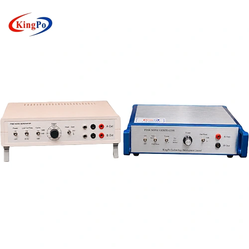
Set the audio amplifier operating condition based on delivering 1/8 non-clipping output power to the speaker. In the non-clipping state, adjust the volume so the RMS voltage drops to approximately 35.32% of the value — this is 1/8 non-clipping output power. Since pink noise more closely resembles real-world sound, after obtaining non-clipping output power with a 1000 Hz sine wave, switch to pink noise as the signal source. When using pink noise, add a bandpass filter (as shown in the figure below) to limit the noise bandwidth.


Normal and Abnormal Operating Conditions — Normal Operating Conditions
When setting normal operating conditions for different types of audio amplifier equipment, consider all the following:
- Audio amplifier output connected to the most unfavorable rated load impedance, or the actual speaker (if provided);
- All audio amplifier channels operating simultaneously;
- For organs or similar instruments with tone generator units, do not use 1000 Hz sine wave; instead, arbitrarily combine pressing two bass pedals (if present) and ten manual keys. Activate all stops and keys that increase output power, and adjust the instrument to 1/8 maximum output power;
- If the intended function of the audio amplifier depends on the phase difference between two channels, apply a 90° phase difference between the signals on the two channels;
- For multi-channel audio amplifiers where some channels cannot operate independently, connect rated load impedance and adjust output power to the 1/8 non-clipping output power designed for the amplifier;
- If continuous operation is not possible, operate the audio amplifier at the maximum output power level allowed for continuous running.
Normal and Abnormal Operating Conditions — Abnormal Operating Conditions
Abnormal operating conditions for audio amplifiers are based on normal conditions but simulate the most unfavorable situations possible, such as adjusting volume to make the speaker operate at the most adverse point between zero and maximum output power, or setting short-circuit conditions on the speaker, etc.
Normal and Abnormal Operating Conditions — Temperature Rise Test Placement
During temperature rise testing of audio amplifiers, place the equipment according to the manufacturer’s declared position. If no special declaration is made, place the equipment in a front-open wooden test box, 5 cm from the front edge of the box, with 1 cm free space along the sides or top, and 5 cm from the rear of the box to the equipment back — overall placement simulating a typical home TV cabinet.
Normal and Abnormal Operating Conditions — Noise Filtering and Fundamental Wave Recovery
Some digital amplifier circuits transmit noise along with the audio signal to the speaker, causing disordered clutter on the oscilloscope when monitoring the speaker output waveform. It is recommended to use the simple signal filtering circuit shown below (connection method: points A and C to speaker output terminals, point B to audio amplifier reference ground/return ground, points D and E to oscilloscope probe). This can filter out most clutter and largely recover the 1000 Hz sine fundamental wave (note: 1000F in the figure is a typo and should be 1000 pF).
For some high-performance audio amplifiers that can eliminate peak distortion issues, allowing no visible distortion or clipping even at maximum output power, the non-clipping output power equals the maximum output power. When clipping cannot be visibly established, treat the maximum output power as non-clipping output power.
[IMAGE_PLACEHOLDER: Simple signal filtering circuit]
Audio Signal Electrical Energy Source Classification and Safety Protection
Audio amplifiers can amplify and output high-voltage audio signals, so the audio signal must be classified as an electrical energy source and provided with safety protection. During classification, set the tone controls to balanced position so the audio amplifier operates at the state delivering maximum non-clipping output power to the speaker, then remove the speaker and test open-circuit voltage. See the table below for audio signal electrical energy source classification and safety protection:
|
Electrical Energy Source Classification and Safety Protection |
|||
|---|---|---|---|
| Energy Source Class | Audio Signal RMS Voltage (V) | Examples of Safety Protection Between Energy Source and Ordinary Persons | Examples of Safety Protection Between Energy Source and Instructed Persons |
| ES1 | ≤71 | No safety protection required | No safety protection required |
| ES2 | >71 and ≤120 | Terminals insulated (accessible parts non-conductive): Mark with ISO 7000 symbol 0434a or 0434b | No safety protection required |
| Terminals not insulated (conductive terminals or bare wires): Mark with indicative safety warning, e.g., “Contact with uninsulated terminals or wires may cause discomfort” | |||
| ES3 | >120 | Use connectors compliant with IEC 61984 and mark with IEC 60417 symbol 6042 |
FAQs – IEC 62368-1 Audio Amplifier Test Requirements – Common Questions & Answers
Q1: Why must 1000 Hz be used as the reference signal? What if the amplifier has poor response at 1000 Hz? A: According to ITU-R 468-4, the frequency response at 1000 Hz is defined as 0 dB, making it the standard reference point for audio noise measurement and consistent comparison of amplifier frequency response performance. If the manufacturer declares that the amplifier is “not intended to operate at 1000 Hz” (e.g., some professional musical instrument amplifiers or designs optimized for specific frequency bands), the peak response frequency may be used instead: fix the signal source amplitude, sweep the frequency, and select the frequency at which the maximum RMS voltage appears across the rated load (loudspeaker). This becomes the substitute reference signal.
Q2: How exactly do we distinguish between maximum output power and non-clipping output power? A:
- Maximum output power: Apply a 1000 Hz sine wave; the amplifier enters the saturation region, the output waveform shows flat-top clipping, and the crest factor drops below 1.414 (typically 1.37–1.38). Monitor the loudspeaker terminals with an oscilloscope to confirm clipping.
- Non-clipping output power: From the maximum output power state, back off (reduce gain) until the amplifier operates at the boundary between the amplification and saturation regions. The waveform becomes a clean sine wave with no visible clipping, and the crest factor returns to ≈1.414. (If slight amplitude jitter occurs at the exact boundary, use 50% of the peak-to-peak voltage as the peak value for crest factor calculation.) The RMS voltage at this point is lower than at maximum output power. These are two sequential states in the same test procedure. Non-clipping output power is the most commonly used reference for “normal operating conditions” in safety testing.
Q3: Why do we adjust the volume (gain) instead of the signal source amplitude when backing off from maximum to non-clipping output power? A: Adjusting the signal source amplitude provides coarse control. Due to the high gain of the amplifier, even a small change in source amplitude causes a large jump in output power (e.g., in the original Figure 4, backing off by reducing source amplitude only achieves 4.066 V RMS, while adjusting volume reaches 4.632 V RMS — a ~30% power difference). Correct method: Fix the signal source amplitude and adjust the equipment’s own volume control / gain until clipping just disappears. This better reflects real usage and aligns with the intent of Annex E.1.
Q4: Where does the 1/8 non-clipping output power come from? Why 1/8 and not another ratio? A: Real-world music and speech signals typically have a crest factor ≤4 (example in original Figure 5 shows ≈4). To reproduce a crest factor = 4 signal without distortion, the amplifier must handle the peak without clipping. Using a 1000 Hz sine wave (crest factor = 1.414) as reference, if the target signal peak is 3.490 V, the required sine-wave RMS to avoid peak clipping would be 3.490 / 1.414 ≈ 2.468 V. However, the actual target signal RMS is only 0.8718 V. The voltage ratio is ≈0.3532, and the corresponding power ratio is 0.3532² ≈ 0.125 = 1/8. Thus, setting the amplifier to deliver 1/8 non-clipping output power (based on the 1000 Hz sine reference) corresponds to the optimal operating point for distortion-free reproduction of a typical real-world signal with crest factor ≈4. In practice: first adjust to 1/8 non-clipping with sine wave (RMS ≈35.32% of maximum non-clipping RMS), then switch to pink noise + bandpass filter.
Q5: Why is a bandpass filter required when using pink noise? A: Pink noise has a very wide spectrum (20 Hz–20 kHz). Feeding it directly can overload the amplifier at certain frequencies or introduce excessive high-frequency noise that makes the oscilloscope waveform look chaotic and hard to judge for clipping. Adding a bandpass filter (typically limiting to the effective audio band, as shown in the original circuit) removes out-of-band noise, making the waveform cleaner and closer to real audio for accurate RMS measurement and clipping assessment.
Q6: How should normal operating conditions be set for multi-channel amplifiers or channels that cannot operate independently? A:
- Connect the most unfavorable rated load impedance to all channels;
- Operate all channels simultaneously;
- For channels that depend on others (e.g., internal linkage in a power IC), still connect rated loads and set to the designed 1/8 non-clipping output power;
- For equipment that cannot run continuously at full power (e.g., some professional amplifiers with thermal protection), use the manufacturer’s declared maximum continuous operating power as the normal condition.
Q7: What are the main worst-case scenarios simulated by abnormal operating conditions? A: Abnormal conditions build on normal conditions but introduce the most severe plausible single faults, such as:
- Volume set to any point between 0 and maximum (especially the position causing highest temperature rise);
- Loudspeaker short-circuited;
- Loudspeaker open-circuited;
- Abnormal signal source (e.g., DC offset);
- Other faults that could lead to overheating, overload, or uncontrolled energy release. These are used to verify that temperature, insulation, and protection still meet safety requirements (see Annex E.2, B.3, B.4).
Q8: How should the equipment be positioned during temperature rise tests? A: Position the equipment according to the manufacturer’s declared installation. If no specific declaration exists, use the typical home TV cabinet simulation:
- Front-open wooden test box;
- Equipment front edge 5 cm from box front edge;
- 1 cm clearance on sides and top;
- 5 cm clearance between equipment rear and box rear wall. This arrangement mimics common household installation environments.
Q9: Digital amplifiers output messy waveforms with lots of switching noise — how to clearly see clipping on the oscilloscope? A: Use the simple filtering circuit recommended in the original article (points A & C to loudspeaker terminals, B to reference/return ground, D & E to oscilloscope probe, including the 1000 pF capacitor, etc.). This removes most high-frequency switching noise, allowing the 1000 Hz fundamental sine wave to be recovered clearly for clipping judgment. Note: the original diagram labels “1000F” is a typo and should read 1000 pF.
Q10: What if the amplifier shows no visible clipping even at maximum output power? A: Some high-performance Class D or other well-designed amplifiers remain free of visible clipping/distortion even at their maximum rated output. In such cases, treat the measured maximum output power as the non-clipping output power — no further back-off is needed — and proceed with subsequent tests (1/8 power, temperature rise, etc.) using that value.