Shan Chao 1 , Qiang Xiaolong 2 , Liu jiming 3 , Zhang Chao 3 .
(1. Heilongjiang Institute for Drug Control, Harbin 150088, China ; 2. Guangxi Zhuang Autonomous Region Medical Device Testing Center, Nanning 530021, China ; 3. Kingpo Technology Development Limited Dongguan 5 23869 ; China )
Abstract: High-frequency electric-knife units are indispensable equipment in modern surgical procedures, utilizing high-frequency electrical currents to cut or coagulate tissues for rapid hemostasis and tissue removal. This paper presents the design and implementation of a high-frequency electric-knife analyzer based on oscilloscope technology. The analyzer enables real-time monitoring and analysis of key parameters such as output waveform, frequency, and power of high-frequency electric-knife units [1] . It supports multiple testing and calibration modes, featuring high bandwidth, large dynamic range, high accuracy, automation, and compatibility with various pulse modes. This instrument provides a robust tool for performance evaluation and optimization of electric-knife units, meeting the requirements of most testing and calibration scenarios for high-frequency electric-knife devices. This research has overcome core technical barriers, successfully developing an electric-knife analyzer with fully proprietary intellectual property rights. It fills the gap in domestic high-end equipment within this field, marking a milestone in advancing the high-frequency surgical device industry and reducing procurement and operational costs for medical institutions.
Keywords: High-frequency electr ic-knife analyzer, Oscilloscope, Testing and calibration, Proprietary intellectual property
0 Introduction
Since its introduction in the early 20th century, high-frequency electrosurgical units have been widely used in surgery due to their efficient and precise cutting and coagulation capabilities. A comprehensive analysis of the performance of high-frequency electrosurgical units, accurately understanding their output characteristics , and eliminating the influence of factors such as electromagnetic fields on their normal operation to ensure their safety are of great significance for improving surgical quality and protecting patient safety.
This paper describes the development of a high-frequency electrosurgical analyzer based on an oscilloscope. Relying on mature oscilloscope products currently on the market, it develops a matching load circuit, relay switching circuit, signal conditioning circuit, non-contact current probe, and dedicated coupling circuit. On this hardware basis, it develops matching testing software to accurately measure and analyze the output parameters of the high-frequency electrosurgical unit (such as power, voltage, current, frequency, etc.) to ensure that the equipment meets safety and effectiveness standards.
The innovation of this research lies in breaking through the technical bottlenecks of domestically produced high-frequency electrosurgical analyzers in areas such as signal processing, dynamic load simulation, and safety detection algorithms, achieving complete independent intellectual property rights for this type of equipment for the first time. Its successful development not only fills the gap in domestic high-end medical testing equipment but also helps promote the localization of the medical equipment industry chain, reduces medical institutions’ dependence on imported equipment, and provides important technical support for improving the management level of operating room equipment and patient safety assurance capabilities in my country.
1. Working principle of high-frequency electrosurgical analyzer
The high-frequency electrosurgical analyzer is a professional instrument used to detect and calibrate the performance of high-frequency electrosurgical devices. Its working principle is mainly based on the accurate measurement and analysis of the output parameters of the high-frequency electrosurgical device [1] (such as power, voltage, current, frequency, etc.) to ensure that the device meets the safety and effectiveness standards [ 3 ] . The high-frequency electrosurgical analyzer needs to detect the key parameters of the high-frequency electrosurgical device, including:
(1) Output power: Ensure that the actual power is consistent with the set value.
(2) Voltage and current waveforms: Verify the stability and waveform integrity of high-frequency signals.
(3) Frequency: Ensure that the high-frequency signal is within a safe range (avoid low-frequency current from causing muscle or nerve stimulation).
(4) Safety parameters: high frequency leakage current , surgical electrode leakage current and bipolar electrode leakage current [ 2 ] etc.
Its working principle can be summarized in the following steps:
(1) Signal acquisition: High-frequency current and voltage signals (frequency is usually 300kHz–5MHz) output by the electrosurgical unit are captured in real time through high-precision sensors and coupling circuits.
(2) Signal conditioning and conversion: High-frequency signals are filtered, attenuated and isolated to eliminate electromagnetic interference, and high-voltage signals are converted into low-voltage signals within a safe range for subsequent analysis;
(3) Measurement of key parameters
Power: Based on the true RMS algorithm and combined with dynamic load simulation (0–6400Ω), the actual output power of the electrosurgical unit under different tissue impedances was measured.
Frequency: The signal spectrum is analyzed using Fast Fourier Transform (FFT) to ensure that the main frequency meets medical standards;
Waveform analysis: Detects the integrity of waveforms (such as continuous waves in cut mode and pulse waves in solidification mode) and identifies abnormal oscillations or distortions;
Leakage current detection: measure the high-frequency leakage current of the equipment , the leakage current of the surgical electrode and the leakage current of the bipolar electrode [ 2 ] to ensure compliance with safety limits (such as JJF1217-2025 standard).
REM test: Adjust the resistor to outside the alarm range (e.g., >135Ω or <5Ω), and confirm that the device issues an audible and visual alarm and stops output;
Automated calibration and output: Automatically determines whether parameters are qualified according to preset standards (such as JJF1217-2025), generates test reports, and guides equipment debugging or maintenance.
2 Design of a High-Frequency Electrosurgical Unit Based on an Oscilloscope
2.1 System Architecture
The system architecture of the high-frequency electrosurgical analyzer mainly includes an electronic load module, a signal acquisition and processing module, a control module, a display and operation module, and an external remote module , as shown in Figure 1 .
Electronic load module : includes filter circuit, amplifier circuit and analog-to-digital conversion circuit, which filters, amplifies and converts the acquired signal to digital to facilitate subsequent data processing and analysis [4].
Signal acquisition and processing module : It consists of a high-frequency current probe and an oscilloscope module . The high-frequency probe is used to acquire the high-frequency current signal output by the electric knife, and the oscilloscope is used to convert the analog signal into a digital signal [4] .
Control module: Includes temperature control module and electronic load control module. Temperature control module is used to monitor and control the temperature of electronic load to ensure that electronic load works normally at a certain temperature. Electronic load control module is used to control the load setting on the high-frequency electrosurgical unit, realize 1Ω load step, and switch between different circuits in different test modes.
Display and Operation Module : Composed of an LCD display and USB peripherals , it is used to display the output parameters and waveforms of the electrosurgical unit, as well as to control the operation of the analyzer.
External remote module : Through the external HTTP interface, automated control of the instrument can be achieved, which facilitates automated testing by relevant R&D personnel and improves testing efficiency; the WiFi module is used for remote system or firmware updates, which facilitates subsequent use and maintenance of the instrument .

Figure 1. System architecture of the high-frequency electrosurgical analyzer
2.2 Instrument Hardware Design
In the hardware design stage of the test instrument, the test functions and indicators need to be determined first. By analyzing the high frequency electrosurgical analyzers currently on the market, and then combining the “High Frequency Electrosurgical Calibration Specification” (JJF 1217-2025) [2] , the following technical indicators are compiled.
The functional requirements and technical specifications are shown in Table 1:
Table 1 Design technical parameters of high frequency electrosurgical analyzer
| Performance parameters | Technical indicators |
| power | Measuring range: 1-500W (rated load 200Ω)
Resolution: 0.1W Accuracy: (10,50]W: ±(5.0%×P+0.1)W (50,400]W: ±5.0% |
| Current | Measurement range: 20mA~1000mA RMS
Resolution: 0.1 mA Accuracy: ±(2.5%×I+mA) |
| Voltage | Measurement range: 0-5kV (peak value) |
| bandwidth | 30kHz-200MHz (Measurement Module) |
| Internal load impedance | 0-6400 Ω , in 1 Ω increments
Accuracy: ±1% (>=50 Ω ) |
| Fixed non-inductive resistor | 200 Ω
Accuracy: ±1% |
| Peak factor | 1.2-500, resolution: 0.1 |
| Power distribution curve | The host screen displays a distribution curve and can be extended by connecting an external screen. |
| REM/ARM/CQM testing | This is achieved using a 500Ω adjustable load, in 1Ω increments. |
| Automated testing functionality | It can output composite pulse waveforms and has an automatic power distribution curve. |
| physical parameters | Display: 10-inch full-color LCD touchscreen, supports graphics, test curves
Display and zoom; Dimensions: 500*450*220mm; Weight: 10Kg |
During the hardware development phase, a systematic design verification process was used to rigorously test key performance indicators. Based on the structured verification of the hardware design flowchart, signal chain integrity verification, dynamic load adaptability debugging, and security isolation performance evaluation were completed sequentially to ensure that the functions of each module were highly matched with the preset technical specifications (e.g., bandwidth ≥200MHz, power accuracy ≤5%). Through multiple rounds of precision calibration and parameter optimization, the core technical parameters were ultimately made to meet the design requirements (see Table 1 for details).
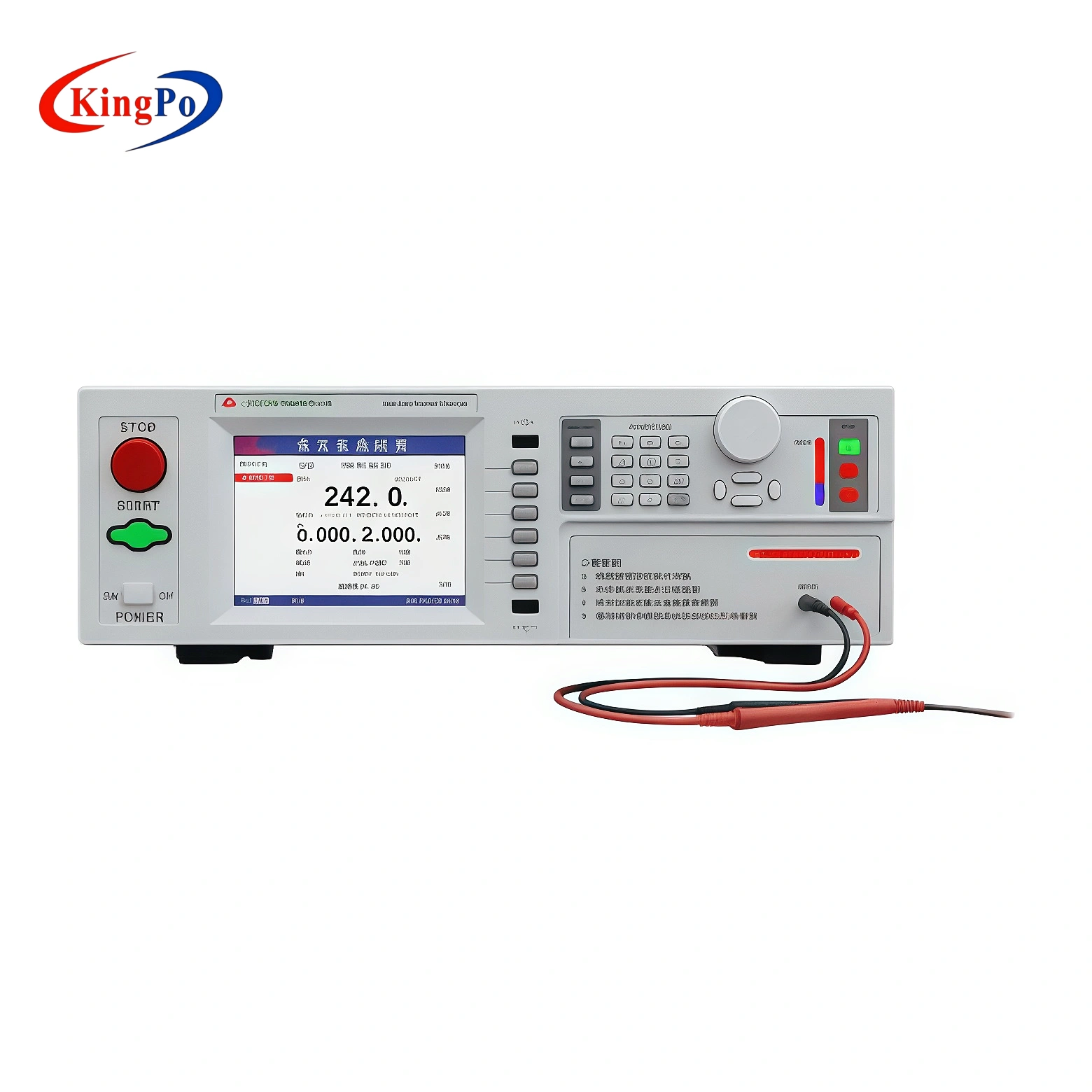
In the industrial design phase, after multiple iterations and ergonomic simulation optimization, the final instrument appearance (as shown in Figure 2) combines a minimalist style with functional requirements, adopts an anti-interference metal shell and a highly visible touch interface, and takes into account both ease of operation and laboratory suitability.

Figure 2. Prototype appearance of the high-frequency electrosurgical analyzer
In the circuit design, an electronic load module consisting of 13 high-frequency non-inductive high-power resistors was designed, which can realize the resistance value of 1Ω from 0 to 6400Ω [4] . In addition to being connected in series, each resistor is connected in parallel with a high-voltage relay. In this way, by controlling the on and off of the high-voltage relay, the total resistance value of the circuit can be changed. The measurement module consists of a high-frequency current probe, which contains a data acquisition circuit including an amplifier circuit and a filter circuit, as shown in Figure 3. The relay is controlled by the system control module and is controlled by two IO expanders_MCP23017 chips respectively. The MCP23017 chip is a 16-bit general-purpose parallel I/O expansion provided by the I2C bus.
The MCP23X17 consists of multiple 8-bit configuration registers for input, output, and polarity selection. The system master device can enable I/O as input or output by writing to the I/O configuration bit (IODIRA/B). Data for each input or output is stored in the corresponding input or output register. The polarity of the input port register can be inverted using the polarity inversion register. All registers are readable by the master system.

Figure 3 Circuit diagram of high-frequency electrosurgical analyzer
2.3 Software Implementation for Testing Instruments
In designing the software for the high-frequency electrosurgical analyzer based on the oscilloscope, a set of efficient and accurate processing programs were constructed. First, a high-precision current probe was used to collect high-frequency current signals. The analog signals were converted into digital signals through a filtering and amplification circuit. Accurate and fast frequency domain analysis was performed. Fast Fourier Transform (FFT) was used. Then, the actual effective current value was calculated. The core function of the software is to set different load resistance values. The effective current signals collected under different loads will be converted into power values and various target parameters will be calculated: voltage value (RMS, PK, MAX), peak factor, duty cycle, frequency, pulse period, etc. [5] .
The software interface of the tester is shown in Figure 4. The left side has the functional module area, test waveform diagram, and test operation area at the top and bottom, respectively. The right side has the parameter setting area and data display area at the top and bottom, respectively. The test data is displayed, including current value, voltage value (RMS, PK, MAX), power value, frequency, and peak factor. In different test modes, the parameter settings and data display content change synchronously accordingly.

Figure 4. High-frequency electrosurgical analyzer test software
Table 2 Introduction to the Software Interface Functions of the High-Frequency Electrosurgical Unit Analyzer
| serial number | Area Name | Function |
| 1 | Functional module area | Switch between different test functions, including: power test, load curve test, leakage current test, REM test, and system parameter settings. |
| 2 | Test waveform area | It can display test waveforms, providing a clear and intuitive view of the waveform curves output by the high-frequency electrosurgical unit, facilitating analysis and observation. |
| 3 | Test operation area | Includes test start, pause, and end function buttons. |
| 4 | Parameter setting area | Different test parameters can be set depending on the different test functions. |
| 5 | Data display area | Display the test results data. |
3. Calibration of the high-frequency electrosurgical analyzer
In the calibration specification for high frequency electrosurgical knife (JJF_1217-2025), specific technical parameter requirements are put forward for the testing device of high frequency electrosurgical knife tester, as shown in Table 3. Therefore, the verification of high frequency electrosurgical knife analyzer should be carried out in accordance with these technical requirements [6] .
Table 3 Technical Requirements for High-Frequency Electrosurgical Unit Calibration Device
| Serial Number | Parameter name | Measurement range | Maximum permissible error |
| 1 | High frequency power | (1~500)W | (10,50 ] W : ±(5% x P+0.1W) |
| (50, 400]W: ±5% | |||
| 2 | High-frequency leakage current | (20~1000)mA | ± (2.5% x I + 1mA) |
| 3 | Variable load resistance R | (50~2000)Ω | ±2.5%, step value: 25Ω |
| 4 | Fixed non-inductive resistor R | 200Ω | ±1% |
| 5 | Operating frequency | (0.3~5.0MHz) | ——- |
3.1 Setting up the testing environment
Testing environment requirements:
Ambient temperature: (15~30)℃;
Relative humidity: ≤80%;
Power supply: Voltage: (220±11)V, Frequency: (50±1)Hz;
There should be no mechanical vibrations or electromagnetic interference in the surrounding area that could affect normal operation.
Measurement standards and other equipment
(1) Multi-function table
Resistance measurement range: (0~10) KΩ, maximum permissible error: ±0.5%.
(2) Standard apparatus for high-frequency electrosurgical analyzer
High-frequency power (frequency: 0.3 MHz~5 MHz): Measurement range: (1~500) W, maximum permissible error: ±0.5%.
High-frequency current (frequency: 0.3 MHz~5 MHz): Measurement range: (0.001~1.5) A, maximum permissible error: ±0.5%.
Note: Other standard equipment that meets the maximum permissible error requirement is permitted.
After preparing the calibration equipment, instruments, and site environment according to the above requirements, the calibration site environment for the high-frequency electrosurgical analyzer is set up as shown in Figure 5.

Figure 5. Setup of the calibration environment for the high-frequency electrosurgical analyzer
3.2 Verification of high-frequency power
The connection between the high-frequency electrosurgical analyzer and the standard device of the high-frequency electrosurgical analyzer is shown in Figure 6. Connect the two ends of the power measurement of the high-frequency electrosurgical analyzer to the power output end of the calibration device, and then set the corresponding output power on the calibration device [ 7 ] .

Figure 6 Wiring diagram for power calibration of high-frequency electrosurgical analyzer
The high-frequency power should be determined according to the measurement range of the high-frequency electrosurgical analyzer, and calibration points should be set as needed, generally no less than 5 calibration points (including the upper and lower limits of the measurement range). The measured value of the high-frequency power of the standard device and the corresponding displayed value of the high-frequency power of the high-frequency electrosurgical analyzer should be read and recorded in the original record table. The results are shown in Table 4.
Table 4 AC power calibration data of high-frequency electrosurgical analyzer
| serial number | load
(Ω) |
Value to be checked
(W) |
Measured value
(W) |
error
(%) |
Maximum permissible error (%) | in conclusion
(Pass/Fail) |
| 1 | 200 | 10.0 | 10.1 | 0.9 | 5 | P |
| 2 | 20.4 | 20.3 | 0.5 | 5 | P | |
| 3 | 51.6 | 52.8 | 2.2 | 5 | P | |
| 4 | 99.8 | 102.1 | 2.2 | 5 | P | |
| 5 | 149.7 | 152.6 | 1.9 | 5 | P | |
| 6 | 200.1 | 204.3 | 2.0 | 5 | P | |
| 7 | 251.4 | 250.1 | 0.5 | 5 | P | |
| 8 | 500 | 298.3 | 302.5 | 1.3 | 5 | P |
3.3 Verification of high-frequency leakage current
The verification of high-frequency leakage current and high-frequency power uses the same device connection method. For example, if the high-frequency current is within the range of 20mA to 1000mA, select no less than 5 calibration points (including the upper and lower limits of the measurement range), read the measured value of the high-frequency current of the standard device and the corresponding displayed value of the high-frequency current of the high-frequency electrosurgical analyzer, and record them in the original record table. The results are shown in Table 5.
Table 5 AC current calibration data for high-frequency electrosurgical analyzer
| serial number | load
(Ω) |
Value to be checked
(mA) |
Measured value
(mA) |
error
(%) |
Maximum permissible error (%) | in conclusion
(Pass/Fail) |
| 1 | 200 | 22.33 | 22.41 | 0.35 | 2.5 | P |
| 2 | 50.80 | 50.84 | 0.07 | 2.5 | P | |
| 3 | 70.65 | 70.69 | 0.05 | 2.5 | P | |
| 4 | 80.35 | 80.57 | 0.27 | 2.5 | P | |
| 5 | 101.3 | 99.9 | 1.40 | 2.5 | P | |
| 6 | 770.4 | 776.1 | 0.73 | 2.5 | P | |
| 7 | 995.6 | 1001.2 | 0.56 | 2.5 | P |
3.4 Verification of Variable Load Resistance
The calibration of the variable load resistor is determined according to the actual application range of the high-frequency electrosurgical analyzer. The calibration points are determined as needed, generally no less than 5 calibration points. The connection between the high-frequency electrosurgical analyzer and the digital multimeter is shown in Figure 7.

Figure 7 Wiring diagram for variable resistance calibration of high-frequency electrosurgical analyzer
With the digital multimeter set to the resistance range and the output resistance calibration point of the high-frequency electrosurgical analyzer set, the measured values of the digital multimeter and the displayed values of the high-frequency electrosurgical analyzer were read. The results are shown in Table 6.
Table 6. Verification data of variable load resistance for high-frequency electrosurgical analyzer
| serial number | nominal value
(Ω) |
Measured value
(Ω) |
error
(%) |
Maximum permissible error (%) | in conclusion
(Pass/Fail) |
| 1 | 100 | 100.4 | 0.4 | ± 2.5 | P |
| 2 | 200 | 199.5 | 0.25 | ± 2.5 | P |
| 3 | 300 | 299.2 | 0.26 | ± 2.5 | P |
| 4 | 500 | 498.8 | 0.24 | ± 2.5 | P |
| 5 | 800 | 802.2 | 0.27 | ± 2.5 | P |
| 6 | 1000 | 998.5 | 0.15 | ± 2.5 | P |
| 7 | 2000 | 1997.1 | 0.15 | ± 2.5 | P |
| 8 | 4000 | 3991.9 | 0.20 | ± 2.5 | P |
| 9 | 6000 | 5987.6 | 0.20 | ± 2.5 | P |
3.5 Verification of Fixed Non-Inductive Resistors
The calibration method for fixed non-inductive resistors is the same as that for variable load resistors. The connection diagram of the device is shown in Figure 6. The digital multimeter is set to the resistance range, and the high-frequency electrosurgical analyzer is set to the high-frequency leakage current test mode. The calibration results are shown in Table 7.
Table 7. Verification data of fixed load resistance for high-frequency electrosurgical analyzer
| serial number | nominal value
(Ω) |
Measured value
(Ω) |
error
(%) |
Maximum permissible error (%) | in conclusion
(Pass/Fail) |
| 1 | 200 | 199.1 | 0.45 | ± 1 | P |
4. High-frequency electrosurgical test
4.1 Experimental Environment and Equipment
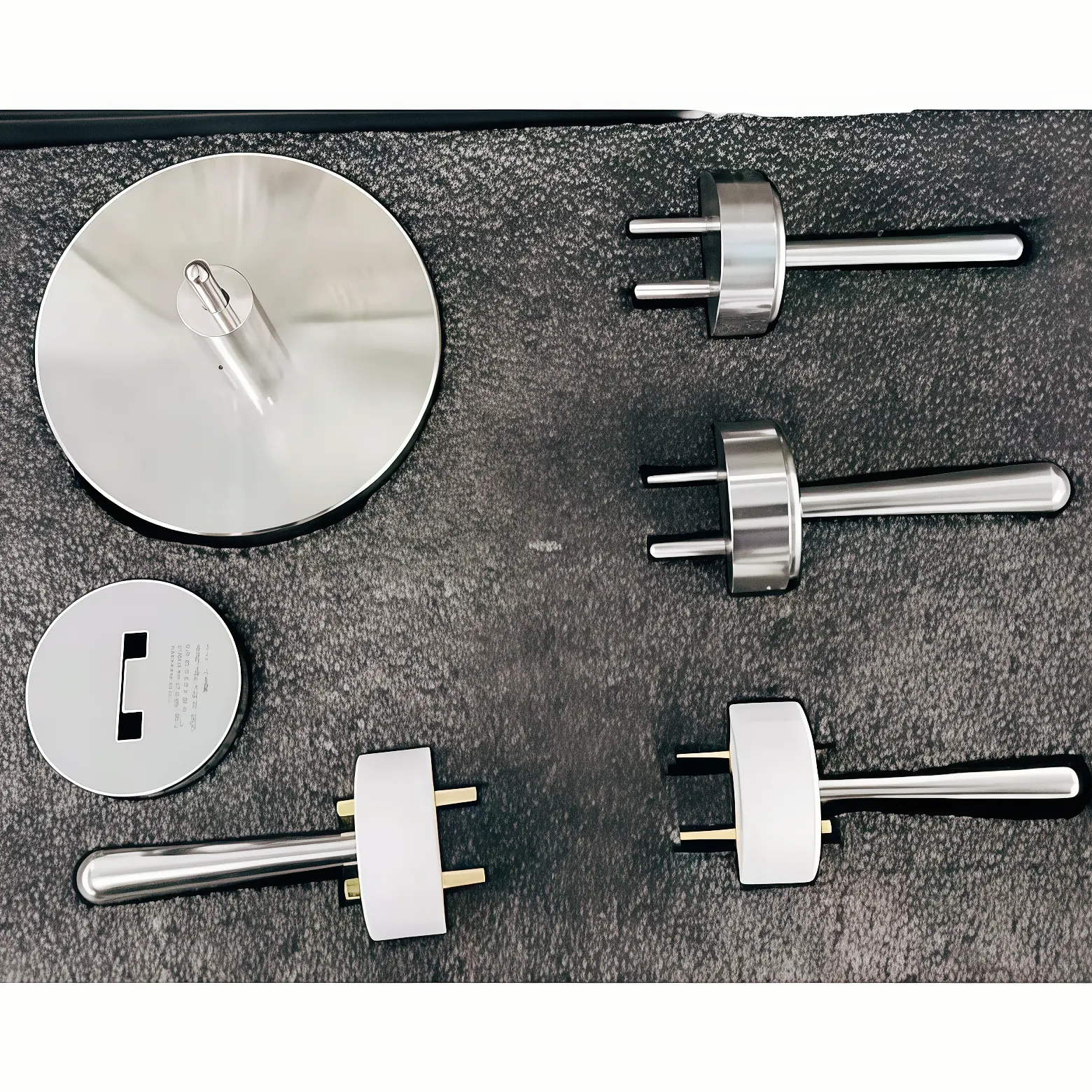
The experiment was conducted in a standard electromagnetic compatibility laboratory with an ambient temperature of 25°C and humidity of 50%. The experimental equipment included a high-frequency electrosurgical unit, a high-frequency electrosurgical analyzer , and a test bench .
This experiment selected three high-frequency electrosurgical units of different brands and models (as shown in Figure 8), basically covering the common high-frequency electrosurgical unit types on the market. The main functions of the products include: electrocutting, electrocoagulation, radiofrequency ablation, and electrocautery. The power distribution is between 0-300W, and the operating frequencies are 300KHz, 500KHz, and 1MHz, respectively. The modes include continuous mode and pulse mode. Specific parameters are shown in Table 8.

Figure 8. Three different types of high-frequency electrosurgical products
Table 8 Technical Specifications of Three High-Frequency Electrosurgical Units
| serial number | Product Name | Function | Operating frequency | Power range | Work mode |
| Product 1 | High-frequency electrosurgical unit | Electrical cutting, electrocoagulation | 300kHz | 0-300W | Continuous mode, pulse mode |
| Product 2 | Radio frequency temperature controlled condenser | Radiofrequency ablation | 500kHz | 0-50W | Continuous mode, pulse mode |
| Product 3 | High-frequency electrocautery therapy device | Electrocautery | 1MHz | 0-20W | Continuous mode |
Based on the triggering mode of high-frequency electrosurgical units, they are divided into unipolar and bipolar types. The test environment setup differs depending on the polarity. The following describes the test environment setup method for power testing and high-frequency leakage current testing in the unipolar operating mode of the electrosurgical unit:
Power test connection method:
As shown in Figure 9, connect the surgical electrode of the electrosurgical unit to the “Active” port of the analyzer, and connect the neutral electrode of the electrosurgical unit to the “Dispensive1” port of the analyzer.

Figure 9 Power test environment setup
High-frequency leakage current test connection method:
As shown in Figure 10, connect the bipolar surgical electrode 1 of the electrosurgical unit to the “Active” port of the analyzer, connect the bipolar surgical electrode 1 of the electrosurgical unit to the “Dispensive1” port of the analyzer, and effectively ground the grounding wire of the high-frequency electrosurgical unit and the “Group” of the analyzer together.

Figure 10. Setup of the high-frequency leakage current test environment
Connect the power supplies to the high-frequency electrosurgical unit and the high-frequency electrosurgical analyzer, and ensure effective grounding. Turn on the high-frequency electrosurgical unit and switch it to working mode. Turn on the high-frequency electrosurgical analyzer, enter the test operation interface, and complete the environment setup and preparation.
3.2 Electrosurgical power test
Electrosurgical power test : Start the high-frequency electrosurgical knife and test it in cutting mode and solidification mode respectively. Monitor the output waveform, frequency, power and other parameters of the electrosurgical knife in real time by the analyzer and record the test data [ 8 ] . In JJF1217-2025 “High-frequency electrosurgical knife calibration specification”, there are the following specific requirements for output power:
The maximum permissible error of the output power indication shall not exceed ±20% of the set value.
The three products were tested separately, and the test results are shown in Tables 9, 10, and 11.
Table 9 Power test data for Product 1
| Electric cutting mode | Electrocoagulation mode | ||||||
| load | Indicated value | Measured value | Power error | load | Indicated value | Measured value | Power error |
| 300Ω | 50W | 53.3W | 6.60% | 300Ω | 10W | 10.6W | 6.00% |
| 300Ω | 100W | 105.4W | 5.40% | 300Ω | 20W | 22.5W | 12.50% |
| 300Ω | 150W | 155.7W | 3.80% | 300Ω | 40W | 37.9W | 5.25% |
| 300Ω | 200W | 210.4W | 5.20% | 300Ω | 60W | 55.4W | 7.66% |
| 300Ω | 250W | 243.5W | 2.60% | 300Ω | 80W | 73.2W | 8.50% |
| 300Ω | 300W | 287.3W | 4.20% | 300Ω | 100W | 91.9W | 8.10% |
Table 10 Power test data for Product 2
| Continuous mode | Pulse mode | ||||||
| load | Indicated value | Measured value | Power error | load | Indicated value | Measured value | Power error |
| 100Ω | 1W | 1.08W | 8.00% | 100Ω | 4W | 4.2W | 5.00% |
| 100Ω | 5W | 5.3W | 6.00% | 100Ω | 8W | 7.8W | 2.50% |
| 100Ω | 10W | 9.8W | 2.00% | 100Ω | 15W | 15.4W | 2.60% |
| 100Ω | 20W | 20.7W | 3.50% | 100Ω | 23W | 23.7W | 3.04% |
| 100Ω | 30W | 29.1W | 3.00% | 100Ω | 28W | 25.8W | 7.85% |
| 100Ω | 50W | 49W | 2.00% | 100Ω | 42W | 38W | 9.50% |
Table 11 Power test data for Product 3
| Full output mode | Half-output mode | ||||||
| load | Indicated value | Measured value | Power error | load | Indicated value | Measured value | Power error |
| 100Ω | 5.5W | 3.2W | 41.80% | 100Ω | 1.7W | 1.2W | 29.40% |
| 200Ω | 9.5W | 6.6W | 30.50% | 200Ω | 2.8W | 2.42W | 13.50% |
| 350Ω | 15.5W | 11.6W | 25.10% | 350Ω | 4.6W | 4.35W | 5.40% |
| 500Ω | 20.6W | 16.7W | 18.90% | 500Ω | 5.9W | 6.3W | -6.70% |
| 1000Ω | 22.8W | 10.2W | 55.20% | 1000Ω | 12.2W | 10.6W | 13.10% |
| 2000Ω | 45W | 11.3W | 74.80% | 2000Ω | 16.5W | 11.1W | 32.70% |
3.3 High-frequency leakage current test
Electrosurgical high-frequency leakage current test : During the operation of the electrosurgical knife, the non-functional current of the output electrode of the high-frequency electrosurgical knife to ground, in JJF1217-2025 “High-frequency electrosurgical knife calibration specification” [2] , the following specific requirements are made for the high-frequency leakage current:
- Neutral electrode leakage current: The high-frequency leakage current flowing from the neutral electrode through a 200Ω non-inductive resistor to ground is no greater than 150mA [ 9 ] ;
- Surgical electrode leakage current: When the neutral electrode is isolated from ground at high frequency, the high-frequency leakage current flowing from the unipolar electrode through a 200Ω non-inductive resistor to ground is no greater than 150mA;
- Bipolar electrode leakage current: The high-frequency leakage current of the bipolar electrode is not greater than ( ) mA (the high-frequency leakage current flowing from each electrode through a 200Ω non-inductive resistor to ground, and the power generated on this impedance is not greater than 1% of the maximum bipolar rated output power).
Product 1 was tested, and the high-frequency leakage current data are shown in Table 12:
Table 12 High-frequency leakage current test data
| Neutral electrode leakage current | Surgical electrode leakage current | ||
| Product Number | Leakage current | Product Number | Leakage current |
| Product 1 | 34.84mA | Product 1 | 108.2mA |
3.4 Testing of the Electrosurgical Unit Negative Plate Resistance Monitoring and Management System
Electrosurgical negative electrode plate resistance monitoring and management system test : While the electrosurgical unit is working, an adjustable resistor (0–500Ω) is used to simulate different resistance values. The test is conducted by connecting to a REM connector or a non-REM connector to monitor the contact resistance between the negative electrode plate and the patient’s skin in real time. When the resistance value exceeds the safe range, the system automatically alarms and stops outputting current to avoid burns caused by insufficient contact area or detachment. The test interface of the instrument is shown in Figure 11.

Figure 11 REM test interface
4. Conclusions and Outlook
This paper designs and implements a high-performance high-frequency electrosurgical analyzer based on an oscilloscope. Through hardware modular design and software algorithm optimization, it successfully solves the technical bottlenecks of domestic analyzers in dynamic load simulation, high-precision signal acquisition and safety detection. Experimental verification shows that the analyzer has high bandwidth (200MHz), wide range (power 0-500W, leakage current 0-1000mA), high precision (power error ≤5%, leakage current error ≤2.5%) and automated testing capabilities, which fully meet the requirements of the JJF1217-2025 calibration specification [2] . In addition, its dynamic load simulation function (0-6400Ω, 1Ω step) and multi-functional test modes (power, leakage current, REM alarm, etc.) provide reliable tools for the performance evaluation and safety calibration of high-frequency electrosurgical units. The research breaks through the technical monopoly of imported equipment, fills the gap in domestic high-end medical testing equipment, and is of great significance for promoting the independent control of the medical equipment industry chain and reducing the operation and maintenance costs of medical institutions.
References
- 202-2021 Medical Electrical Equipment – Part 2-2: Particular requirements for basic safety and basic performance of high-frequency surgical equipment and accessories [S]
- JJF 1217-2025. High-Frequency Electrosurgical Unit Calibration Specification [S]
- Chen Guangfei. Research and design of high-frequency electrosurgical analyzer [J]. Beijing Biomedical Engineering, 2009, 28(4):342-345.
[4] Huang Hua, Liu Yajun. A brief analysis of the power measurement and acquisition circuit design of QA-Es high-frequency electrosurgical analyzer [J]. China Medical Equipment, 2013, 28(01): 113-115.
[5] Chen Shangwen, Performance testing and quality control of medical high-frequency electrosurgical unit [J]. Calculation and Testing Technology, 2018, 45(08):67~69.
[6] Chen Guangfei, Zhou Dan. Research on calibration method of high frequency electrosurgical analyzer [J]. Medical and Health Equipment, 2009, 30(08):9~10+19.
[ 7 ] He Min, Zeng Qiao, Liu Hanwei, Wu Jingbiao (corresponding author). Analysis and comparison of high frequency electrosurgical output power test methods [J]. Medical Equipment, 2021, (34): 13-0043-03 .
[ 8 ] Zhao Yuxiang, Liu Jixiang, Lu Jia, et al. Practice and discussion on quality control and testing methods of high frequency electrosurgical unit. China Medical Equipment, 2012, 27(11):1561-1562.
[ 9 ] Duan Qiaofeng, Gao Shan, Zhang Xuehao. Discussion on high-frequency leakage current of high-frequency surgical equipment. China Medical Device Information, 2013, 19(10): 159-167.
About the Author
About the author: Shan Chao, senior engineer, research interests: quality testing and evaluation of medical device products and related research.
About the author: Qiang Xiaolong, associate chief technician, research interests: quality evaluation and standardization of active medical device testing .
About the author: Liu Jiming , undergraduate degree, research direction : measurement and control design and development .
Corresponding author
Zhang Chao, Master’s degree, major research area is measurement and control design and development, email: [email protected]