A request for a “defibrillator tester” can refer to several completely different laboratory tasks. The correct equipment depends first on the device under test (DUT) and the direction of the defibrillation pulse—not simply on the highest voltage, energy rating or standard number shown on an equipment datasheet.
For an external defibrillator or AED, the DUT generates the therapeutic shock and a defibrillator analyzer receives and measures the output. For an ECG monitor, patient monitor or other patient-connected medical device, the laboratory test system generates the pulse and applies it to the DUT to evaluate defibrillation protection and recovery.
Defibrillation electrode testing and active implantable medical-device immunity testing represent two additional test categories with different test objects, circuits and equipment.
Technical Overview
- External defibrillator / AED: DUT generates the pulse → Defibrillator Analyzer measures it
- ECG / patient monitor: Test system generates the pulse → KP3301 applies it to the DUT
- Defibrillation electrode: Dedicated electrode-performance test circuit → KP-DFT100E
- Active implantable medical device: Controlled immunity pulse → KP-1050S
Which Defibrillation Test Equipment Do You Need?
The fastest way to select the correct system is to identify the DUT before comparing equipment specifications.
| Device Under Test | Main Test Objective | Pulse Source | Correct Equipment Type |
|---|---|---|---|
| External defibrillator / AED | Measure delivered energy, waveform, load response and timing | DUT | Defibrillator Tester / Analyzer |
| ECG / patient monitor / patient-connected equipment | Evaluate defibrillation protection, energy reduction, residual voltage and recovery | Laboratory test system | KP3301 Defibrillation-Proof and Energy Reduction Tester |
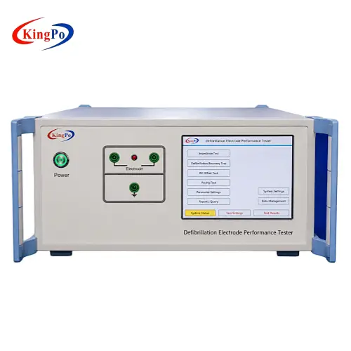
| Defibrillation electrode / pad | Evaluate electrical characteristics and performance associated with defibrillation exposure | Dedicated electrode test circuit | KP-DFT100E Defibrillation Electrode Performance Tester |
| Pacemaker / ICD / active implantable medical device | Apply controlled defibrillation-related immunity conditions and evaluate post-pulse function | Laboratory pulse generator | KP-1050S Defibrillation Test Pulse Generator |
Practical rule: if the DUT generates the therapeutic shock, the test instrument normally receives and measures the pulse. If the DUT must withstand a simulated defibrillation event, the laboratory system generates and applies the pulse.
The Fundamental Difference: Follow the Pulse Direction
Defibrillator Output Testing
Defibrillator → Analyzer
In defibrillator output testing, the external defibrillator or AED is the device under test. It generates the high-energy pulse, and the analyzer receives that pulse through a controlled electrical load.
The engineering question is:
Does the defibrillator deliver the intended electrical output under the defined test conditions?
Defibrillation-Proof Testing
Test System → Patient Connection of DUT
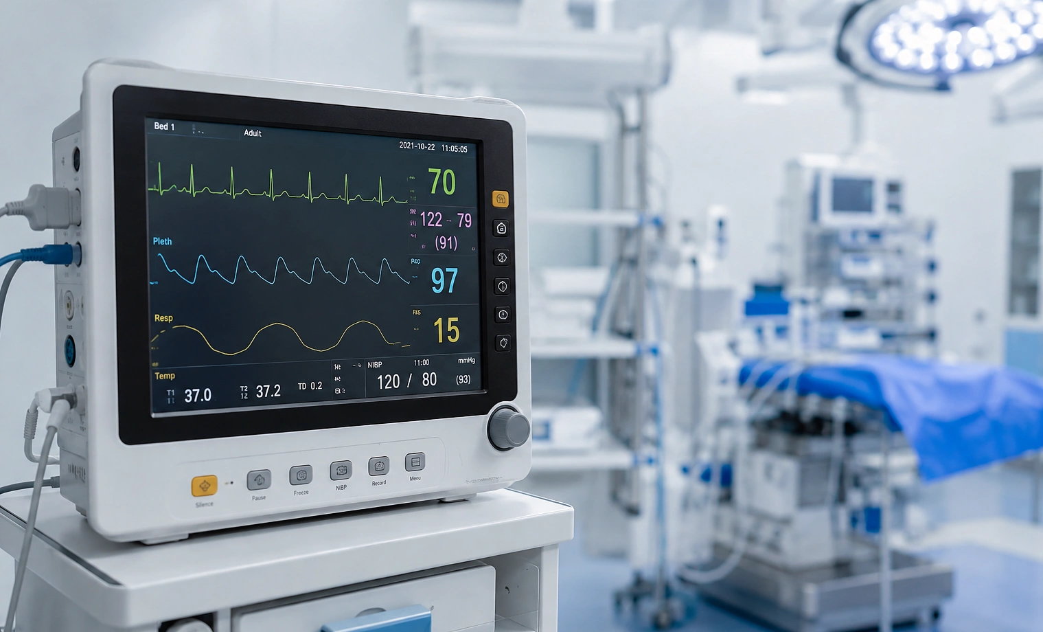
In defibrillation-proof testing, the DUT may be an ECG monitor, diagnostic electrocardiograph, patient monitor or another patient-connected medical device. The laboratory system generates the required electrical test condition and applies it through the specified test circuit.
The engineering question becomes:
Can the medical device withstand the defibrillation-related electrical stress and recover without creating an unacceptable condition?
This opposite pulse direction changes the role of the equipment, connection circuit, measurement point and required evidence. A pulse generator therefore cannot automatically replace a defibrillator analyzer, and a defibrillator analyzer cannot automatically reproduce a defibrillation-proof test network.
1. Defibrillator Output Testing
Defibrillator output testing applies when the DUT is an external cardiac defibrillator, AED, defibrillator-monitor or another device that generates the therapeutic shock.
Typical engineering evidence may include:
- delivered energy;
- voltage and current waveform;
- peak voltage and current;
- biphasic waveform characteristics;
- load-dependent output behaviour;
- charge time;
- synchronized cardioversion timing where applicable;
- repeatability across defined operating conditions.
The complete measurement chain matters. The test result can be influenced by the selected load, output connections, adapters, analyzer input stage, waveform acquisition and data-processing method.
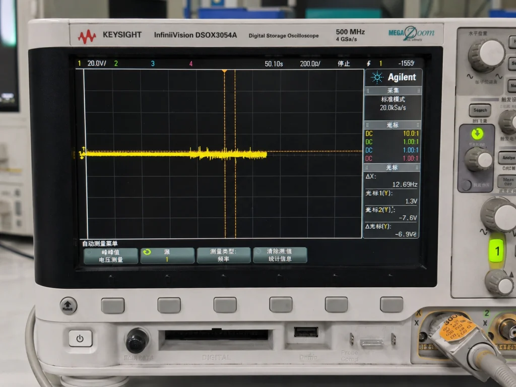
This article does not repeat the detailed energy-integration, waveform, load and timing theory because those subjects are covered separately in our Defibrillator Tester Guide: Energy, Waveform, Load and Timing Measurements.
Important Equipment Boundary
A system used to apply a simulated defibrillation pulse to another medical device is not automatically a defibrillator analyzer. If the DUT is an AED or external defibrillator and the purpose is to measure its delivered output, a dedicated analyzer designed to receive and measure the DUT-generated shock is required.
2. Defibrillation-Proof Testing for Patient-Connected Medical Equipment
Defibrillation-proof testing addresses a fundamentally different situation. The DUT does not generate the therapeutic shock. Instead, a controlled laboratory test condition is applied to its patient connections.
Typical DUTs include:
- ECG monitors;
- diagnostic electrocardiographs;
- multifunction patient monitors;
- ECG lead systems and patient cables;
- other patient-connected input circuits where defibrillation exposure is relevant.
The required evaluation may consider:
- protection of the patient-connected input circuit;
- energy transferred through the protection network;
- residual voltage;
- post-pulse recovery;
- behaviour across required leads or polarities;
- continued function of the relevant medical-device circuitry.
The Test System Is Not Intended to Reproduce a Clinical Defibrillator
A defibrillation-proof test system is a controlled laboratory source. Its purpose is to establish the specified electrical condition at the DUT according to the applicable test circuit and procedure.
The pulse network, polarity, switching sequence, patient connection, return path and measurement location may all affect the result. Selecting equipment from nominal voltage alone is therefore insufficient.
Why the Patient Cable Matters
Where the intended clinical configuration includes a patient cable, the cable can form part of the electrical protection system. It may contain resistance, shielding, insulation, identification networks or other protective elements.
Removing it from the test configuration can therefore change how the defibrillation-related pulse reaches the equipment.
KingPo Equipment for This Test Direction
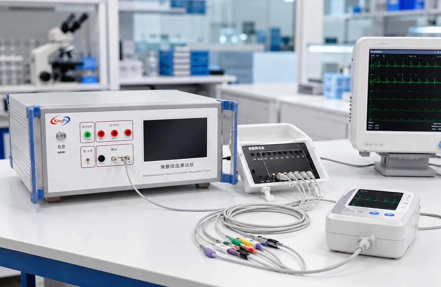
The KP3301 Defibrillation-Proof and Energy Reduction Tester is intended for defibrillation-related protection and energy-reduction testing of patient-connected medical equipment.
KP3301 should not be presented as a direct AED or external-defibrillator output analyzer.
For additional background on this test category, see the Defib-Proof and Energy Reduction Testing Guide.
3. Defibrillation Electrode Performance Testing
A defibrillation electrode is another completely different DUT. Here the laboratory is not measuring the complete defibrillator and is not evaluating an ECG monitor’s patient-input protection.
The electrode or pad itself is under evaluation.
Depending on the applicable electrode specification and test program, engineering evaluation may include characteristics such as:
- electrical impedance;
- behaviour following high-energy exposure;
- DC offset;
- recovery characteristics;
- pacing-related electrical performance where applicable.
The KP-DFT100E Defibrillation Electrode Performance Tester is intended for this electrode-specific test direction.
For a more detailed discussion of electrode testing, see the Defibrillation Electrode Testing Guide.
4. Active Implantable Medical Device Defibrillation Immunity Testing
Active implantable medical devices introduce another test direction. The DUT may be a pacemaker, implantable cardioverter-defibrillator, cardiac resynchronization device or another active implantable cardiovascular system.
In this case, the laboratory generates a controlled defibrillation-related waveform and applies it through the required network while monitoring the behaviour of the implantable device.
The test objective may include:
- application of a defined immunity pulse;
- lead and load simulation;
- monitoring of the DUT operating state;
- evaluation of post-pulse function;
- verification of the required waveform at the test interface.
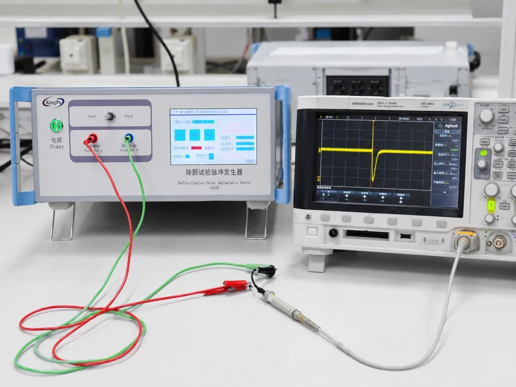
The KP-1050S Defibrillation Test Pulse Generator is intended for this controlled pulse-generation application.
Side-by-Side Comparison
| Engineering Point | Defibrillator Output Testing | Defibrillation-Proof Testing |
|---|---|---|
| Primary DUT | External defibrillator or AED | Patient-connected medical equipment |
| Pulse source | DUT | Laboratory test system |
| Instrument role | Receive, load and measure | Generate, apply and evaluate |
| Main evidence | Energy, waveform, load response and timing | Protection, transferred energy, residual voltage and recovery |
| Typical equipment | Defibrillator Analyzer | KP3301 Defibrillation-Proof and Energy Reduction Tester |
Why Parameter-Only Equipment Selection Fails
Maximum Voltage Does Not Define the Test Method
Two systems with similar peak-voltage specifications can generate completely different waveform shapes, source impedance, pulse duration and energy characteristics.
Nominal Energy Does Not Define the Test Circuit
Energy depends on voltage, current, waveform and load over time. A headline energy value alone does not show whether the equipment can reproduce or measure the required condition.
A Standard Number Is Not an Equipment Specification
A request such as “IEC 60601 defibrillation tester” is incomplete. The applicable part, clause, DUT, pulse direction, circuit and required evidence must be identified before selecting equipment.
Automation Does Not Correct an Incorrect Test Configuration
Automated test sequences can improve repeatability, but they cannot compensate for the wrong load, wrong connection, wrong pulse direction or incorrect test circuit.
Equipment Selection Workflow
- Identify the DUT. Determine whether it is an AED, external defibrillator, ECG monitor, patient cable, electrode pad, pacemaker, ICD or another device.
- Determine the pulse direction. Does the DUT generate the shock, or must the laboratory system apply the shock to the DUT?
- Define the required evidence. Energy and waveform, protection and recovery, electrode characteristics or implantable-device immunity?
- Identify the applicable standard and clause. Work from the authorized standard and project requirements rather than a generic equipment list.
- Review the complete electrical configuration. Include DUT, load, analyzer or pulse source, adapters, patient cable, return path and measurement points.
- Confirm measurement and calibration requirements. The required parameters and operating ranges should be covered by the test and calibration plan.
KingPo Equipment Mapping
| Application | KingPo Equipment | Primary Role |
|---|---|---|
| Patient-connected equipment defibrillation protection | KP3301 | Apply controlled defibrillation-related test conditions to the DUT |
| Defibrillation electrode performance | KP-DFT100E | Evaluate defibrillation electrode electrical performance |
| Active implantable medical-device immunity | KP-1050S | Generate defined defibrillation-related test pulses |
| External defibrillator / AED output measurement | Defibrillator Analyzer | Receive and measure DUT-generated output |
Important: KP3301 and KP-1050S should not be presented as substitutes for a direct defibrillator analyzer used to measure the output of an external defibrillator or AED.
Information to Prepare Before Requesting a Test System
Providing the following information makes equipment selection much more reliable:
- Device under test: AED, external defibrillator, ECG monitor, patient cable, electrode pad, pacemaker, ICD or other device.
- Applicable standard and clause: Include the standard edition or national adoption where relevant.
- Required pulse or measurement: Define whether the requirement concerns delivered energy, waveform, protection, residual voltage, recovery, electrode performance or immunity.
- Connection and load configuration: Include patient cables, lead combinations, adapters, return paths and specified loads.
- Reporting and calibration requirements: State required records, waveform data, report format and calibration expectations.
Frequently Asked Questions
What is the simplest difference between defibrillator output testing and defibrillation-proof testing?
In defibrillator output testing, the DUT generates the shock and the analyzer receives and measures it. In defibrillation-proof testing, the laboratory system generates the pulse and applies it to a patient-connected DUT.
Is KP3301 a defibrillator analyzer?
No. KP3301 is intended for defibrillation-proof and energy-reduction testing of patient-connected medical equipment. It applies the test condition to the DUT rather than measuring the output of an external defibrillator.
Is KP-1050S a defibrillator analyzer?
No. KP-1050S is a defibrillation test pulse generator intended for controlled medical-device immunity testing. It generates the required waveform rather than receiving and measuring an AED or external-defibrillator output.
Which equipment is used for defibrillation electrode testing?
Defibrillation electrode testing requires an electrode-specific test system rather than a standard defibrillator analyzer. KingPo’s KP-DFT100E is designed for this test category.
Why is identifying the DUT more important than starting with the standard number?
Several medical-device tests can involve similar defibrillation-related voltages or waveforms while using completely different pulse directions, circuits and evidence requirements. Identifying the DUT establishes the correct test category before equipment specifications are compared.
Where can I learn more about defibrillator energy and waveform measurements?
For detailed information on delivered-energy calculation, waveform acquisition, load conditions, charge time and synchronization measurements, see the Defibrillator Tester Guide.
Conclusion
Defibrillator output testing and defibrillation-proof testing begin on opposite sides of the energy path. In one case, the DUT generates the therapeutic shock and an analyzer measures the output. In the other, a laboratory system generates the test pulse and applies it to a patient-connected medical device to evaluate protection and recovery.
Defibrillation electrode testing and active implantable medical-device immunity testing require still different equipment. The correct selection sequence is therefore:
DUT → pulse direction → test objective → applicable requirement → test circuit → equipment.
For patient-connected medical equipment, see the KP3301 Defibrillation-Proof and Energy Reduction Tester. For defibrillation electrodes, see the KP-DFT100E Defibrillation Electrode Performance Tester. For active implantable medical-device pulse testing, see the KP-1050S Defibrillation Test Pulse Generator.