Medical Electrical Safety · Technical Delivery Case
KP-DFT201 Defibrillation Effect and Energy Tester Delivered to DEKRA Guangzhou Laboratory
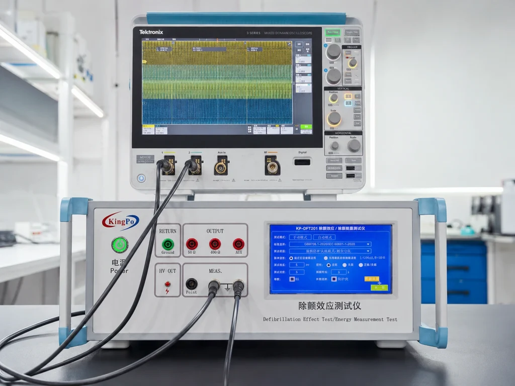
KingPo delivered a KP-DFT201 Defibrillation Effect and Energy Tester to DEKRA Guangzhou Laboratory for medical electrical safety testing. The delivered system supports laboratory work involving protection against defibrillation effects, energy-related measurement, residual-voltage assessment and oscilloscope waveform observation for patient-connected medical electrical equipment.
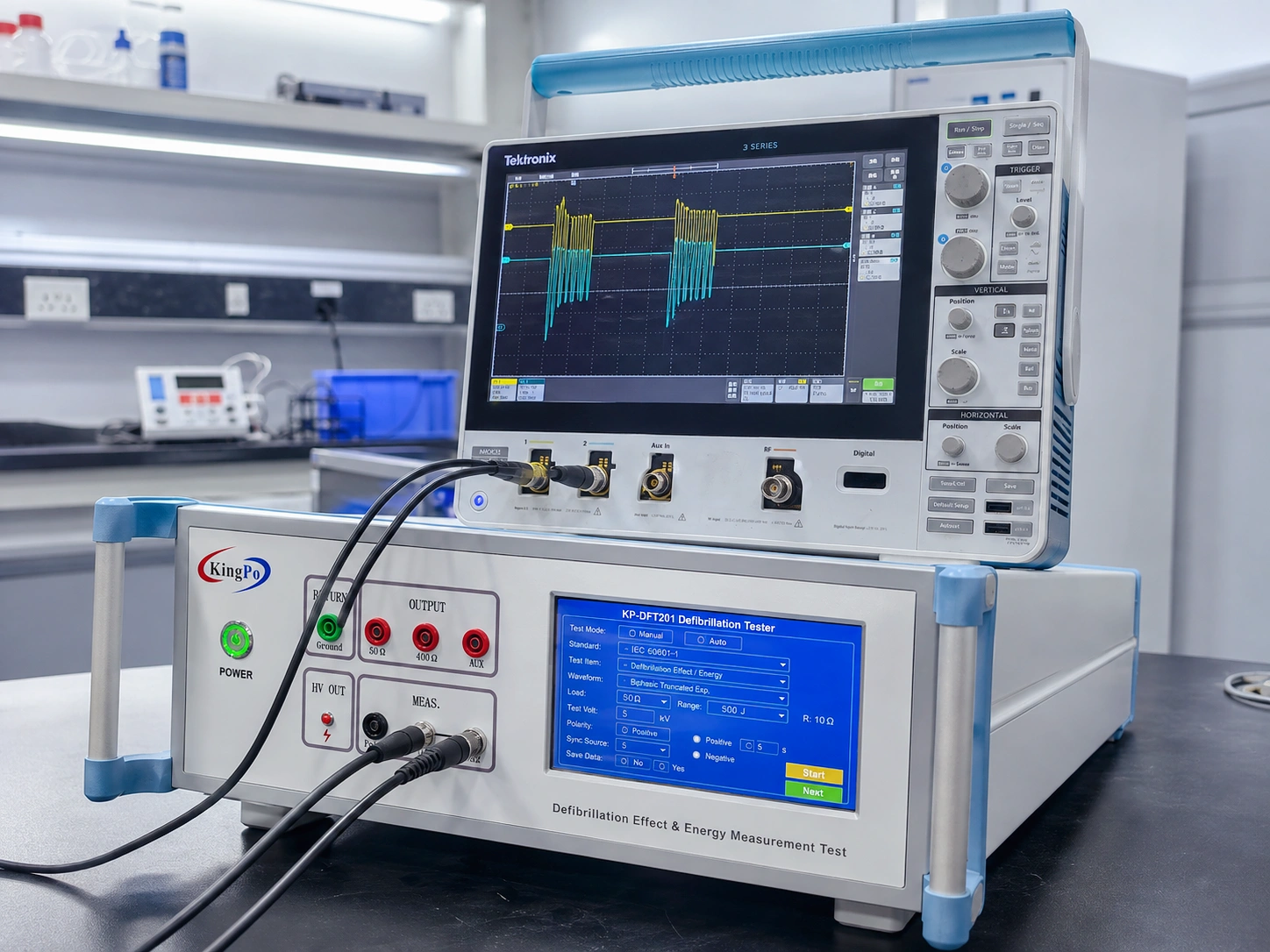
The laboratory setup combines the KP-DFT201 with an external oscilloscope. Test conditions are configured through the tester’s touchscreen, while the oscilloscope provides an independent observation path for the applied waveform and connected measurement channels. This configuration enables the laboratory to review the complete pulse and measurement chain rather than relying on the high-voltage source alone.
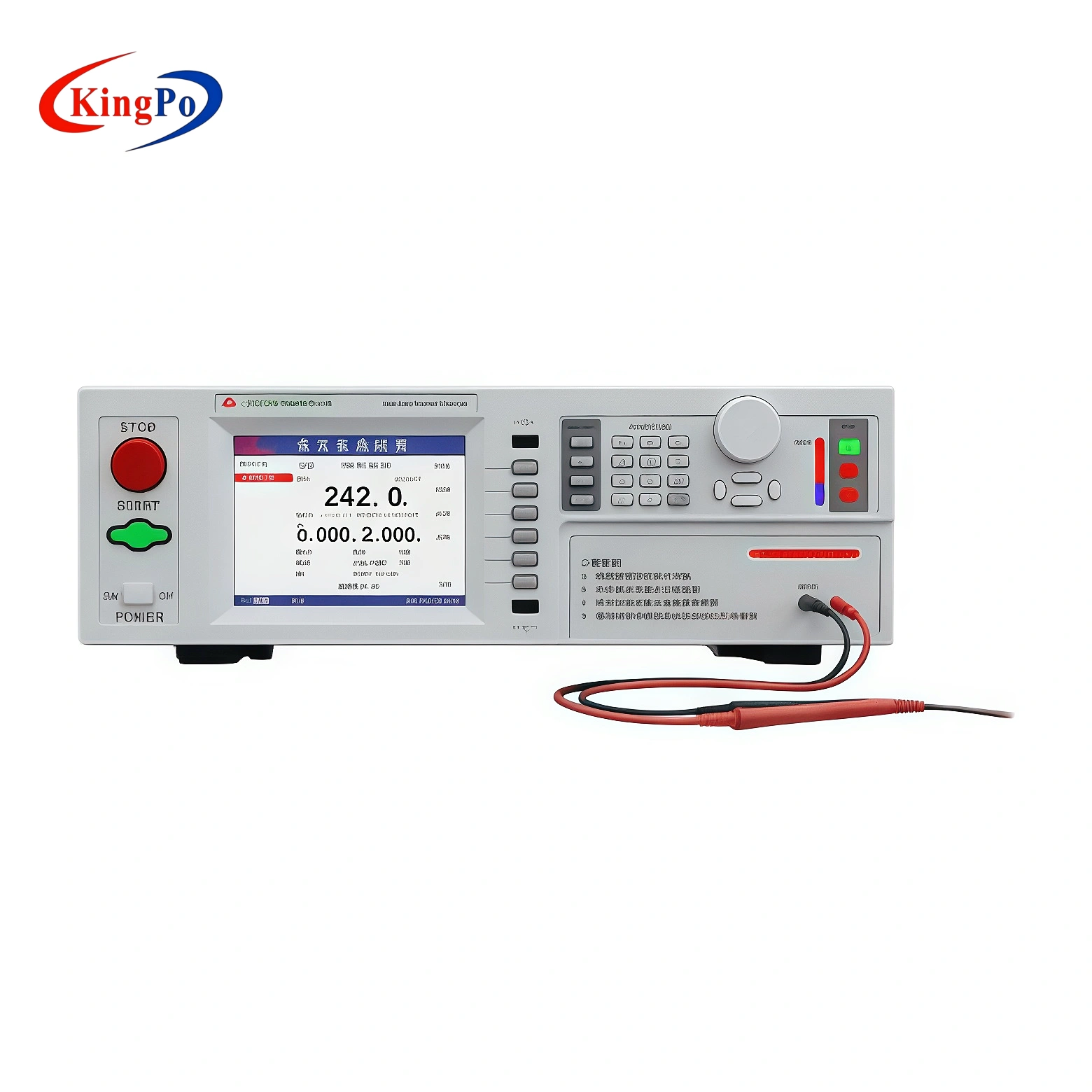
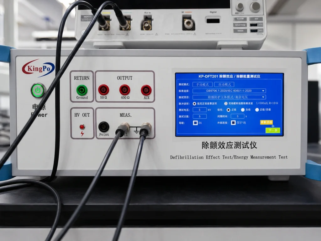
The front panel integrates the high-voltage output, return connection, selectable output terminals and dedicated measurement points required for the test setup. Manual and automatic operating selections are visible on the touchscreen, together with standard selection, test item, voltage, polarity, pulse count, interval and connection settings.
Project Overview
Customer
DEKRA Guangzhou Laboratory
Delivered Model
KP-DFT201
Main Application
Defibrillation effect and energy testing
Measurement Setup
Tester with external oscilloscope
| Primary Test Functions | Protection against defibrillation effects, energy-related measurement, residual-voltage-related assessment and waveform observation |
| Operating Interface | Touchscreen control with manual and automatic test selections |
| External Instrument | External oscilloscope connected to the tester’s measurement terminals |
| Visible Standard Selection | GB 9706.1-2020 / IEC 60601-1:2020 is displayed on the photographed touchscreen |
| Project Evidence | Delivered equipment photographs, front-panel connection details and oscilloscope waveform images |
Delivery Context and Laboratory Objective
The project was configured for a professional third-party medical electrical safety laboratory. In this environment, the tester must support repeatable setup, clearly identified connection points, controlled pulse sequencing and a measurement arrangement that can be reviewed by different laboratory personnel.
A laboratory test system also needs to fit into an existing quality workflow. The operator must be able to record the selected standard, circuit, polarity, test voltage, pulse count, interval, oscilloscope configuration and post-test observations. These records are necessary for repeatability and technical review, even when the tester provides an automatic sequence.
For similar projects, KingPo reviews the medical equipment type, applied parts, patient connections, required common-mode or differential-mode tests, energy-reduction requirements, oscilloscope configuration and calibration scope before confirming the final tester and accessory arrangement.
Laboratory Testing Requirement
Medical electrical equipment connected to a patient may be exposed to defibrillation pulses during clinical use. A laboratory evaluating this type of equipment therefore requires a controlled pulse source and measurement arrangement capable of applying the specified condition while monitoring the response of the equipment under test.
The test cannot be defined only by peak voltage. The applicable circuit, waveform, resistance, inductance, polarity, pulse count, interval, patient connection, operating condition and post-test assessment must all correspond to the relevant standard clause and type of medical electrical equipment.
The selected system needed to support both test execution and waveform review. The KP-DFT201 provides the configurable pulse and connection interface, while the oscilloscope allows the laboratory to observe signals at designated measurement points and confirm that the intended test arrangement has been established.
The delivered configuration is therefore more than a standalone high-voltage source. It is a coordinated test platform involving the pulse source, selected circuit, connection leads, measurement terminals, oscilloscope channels, attenuation arrangement and equipment under test.
How the Defibrillation Effect and Energy Tester Supports Laboratory Testing
Protection against defibrillation effects
This test evaluates the response of patient-connected medical electrical equipment when the specified defibrillation pulse is applied. The selected test path, waveform, polarity, pulse sequence, operating condition and post-pulse evaluation must follow the applicable standard requirements.
Energy reduction and energy-related measurement
The energy-related function is used to evaluate energy behaviour through the configured circuit. Resistance, inductance, waveform, voltage and measurement path must match the required test arrangement rather than being selected only from the maximum capability of the instrument.
Residual-voltage assessment
Where required by the applicable standard, the laboratory may need to evaluate residual or hazardous voltage after the pulse. The measurement point, time window, circuit condition and applicable limit must be established before testing.
Functional recovery and essential performance
The equipment under test may also require functional or essential-performance checks after exposure. A compliant pulse waveform alone does not demonstrate that the medical equipment has met all post-test requirements.
Delivered Equipment and Front-Panel Configuration
The delivered instrument is identified as KP-DFT201. Its front panel integrates the main output and measurement connections required for a controlled defibrillation test setup. The layout separates the high-voltage output from the return path, selectable output terminals and oscilloscope measurement connections.
The touchscreen provides access to the test mode, standard selection, test item, waveform, voltage, polarity, pulse count, interval and connection state. This reduces the need to configure separate external switching devices for every routine sequence, although the operator must still verify the actual wiring before enabling the high-voltage output.
KingPo’s current Defibrillation Effect and Energy Tester series can be reviewed for related configurations. The linked page is a product-family reference; the equipment shown in this delivery case is specifically marked KP-DFT201.
| Visible Interface | Role in the Laboratory Setup |
|---|---|
| HV OUT | Dedicated high-voltage output used for the configured defibrillation pulse path |
| RETURN / Ground | Return connection used to complete the selected test circuit |
| 50 Ω Output | Selectable output terminal used when the applicable circuit requires the corresponding resistance path |
| 400 Ω Output | Alternative output terminal for the relevant configured test path |
| AUX Output | Auxiliary connection used according to the selected test arrangement |
| MEAS. Terminals | Dedicated measurement points for oscilloscope connection and channel comparison |
| Touchscreen Interface | Configuration of the selected standard, test item, waveform, voltage, polarity, pulse sequence and connection status |
What This Tester Is—and What It Is Not
The KP-DFT201 is used to apply simulated defibrillation-related test conditions to patient-connected medical electrical equipment and to support protection, energy-reduction and residual-voltage test workflows.
It should not be confused with a defibrillator analyser used to measure the delivered energy, current, voltage and biphasic waveform of an actual clinical defibrillator or AED under IEC 60601-2-4-related output-performance tests. These are different test objectives and normally require different measurement systems.
Selection mistake to avoid
A request described only as “defibrillation testing” is not technically sufficient. KingPo must first confirm whether the customer needs to test a defibrillator’s output performance, a patient-connected device’s immunity to defibrillation pulses, defibrillation-electrode performance, or an IEC 60601-2-31 test pulse.
Oscilloscope and Waveform Observation Setup
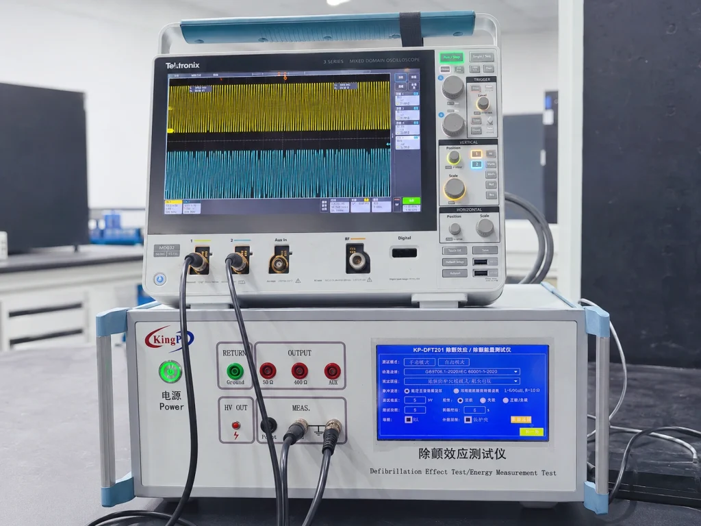
The delivered setup uses an external oscilloscope connected to the KP-DFT201 measurement terminals. Two visible oscilloscope channels allow the laboratory to observe the configured signal and compare the response captured through the selected measurement path.
The oscilloscope is not merely a display accessory. Probe attenuation, input range, vertical scaling, bandwidth, coupling, grounding, trigger source, trigger level and the exact location of each measurement point can all affect the displayed waveform.
Before a trace is accepted as representative, the laboratory should confirm that the oscilloscope probes and measurement channels are suitable for the voltage, frequency content and transient behaviour of the test. The attenuation factor entered into the oscilloscope must correspond to the actual probe or external attenuation network.
Waveform observation is not a pass/fail result
A photograph of a waveform confirms that a signal was displayed during the setup. It does not by itself establish the calibrated amplitude, energy value, measurement uncertainty, applicable limit, functional recovery or final conformity decision.
Test Parameters That Must Be Controlled
The operator should configure and record the complete test condition. Using the correct voltage with an incorrect circuit or measurement path can still produce an invalid test.
| Parameter | Why It Matters |
|---|---|
| Applicable standard and clause | Defines the circuit, pulse condition, specimen state, measurement method and acceptance criteria |
| Common-mode or differential-mode path | Determines how the pulse is applied to the patient connections and reference points |
| Waveform and voltage | Defines the electrical stress applied to the equipment under test |
| Polarity | Some requirements call for positive, negative or both pulse polarities |
| Resistance and inductance | Shape the pulse and determine the energy delivered through the selected test circuit |
| Pulse count and interval | Controls the complete exposure sequence and recovery time between pulses |
| Equipment operating condition | Determines whether normal function, monitoring or essential performance must be maintained during and after exposure |
| Post-test evaluation | Defines residual-voltage, recovery, functional or essential-performance checks required after the pulse sequence |
Why the Complete Measurement Chain Matters
Defibrillation testing involves more than the internal pulse source. The tester, selected output path, circuit components, high-voltage leads, return connection, oscilloscope, probes, attenuation devices, grounding arrangement and equipment under test all influence the measured result.
Test-circuit selection
The laboratory must identify the applicable applied parts, patient connections, test terminals and pulse path before wiring the equipment. A circuit selected for one medical device cannot automatically be transferred to another device with a different patient connection arrangement.
Cable and lead routing
High-voltage output leads and oscilloscope measurement cables should be routed consistently and kept away from unrelated signal cables, accessible conductive parts and operator contact areas. Lead position can influence coupling, noise and repeatability.
Oscilloscope channel assignment
Each measurement point should be linked to a clearly identified oscilloscope channel. Channel labels, attenuation ratios, vertical scales and time-base settings should be recorded in the test sheet so that the displayed traces can be interpreted correctly.
Post-pulse evaluation
After the pulse sequence, the laboratory may need to assess residual voltage, operational recovery, alarms, displayed values, essential performance or other product-specific functions. The required checks should be defined before the pulse is applied.
Recommended Laboratory Test Workflow
A controlled workflow helps reduce wiring errors and prevents a visually acceptable waveform from being mistaken for a complete conformity result.
- Confirm the applicable IEC 60601 or GB 9706 standard, edition, clause and particular-standard requirements.
- Identify the type of medical equipment, applied parts, patient connections, accessible conductive parts and protective-earth arrangement.
- Determine the required pulse circuit, waveform, polarity, resistance, inductance, voltage, pulse count and interval.
- Connect the high-voltage output, return path and equipment under test according to the approved wiring diagram.
- Connect the oscilloscope to the designated measurement points and record the probe or attenuation ratios.
- Confirm channel scaling, coupling, bandwidth, trigger source, trigger level and time base before enabling the pulse output.
- Place the equipment under test in the operating state required by the applicable standard.
- Run the required pulse sequence while maintaining safe clearance from high-voltage connections.
- Record the waveform, measured values, pulse condition and any observed behaviour of the equipment under test.
- Complete the specified residual-voltage, recovery, functional, dielectric or essential-performance assessment after exposure.
Applicable Standards and Test Boundaries
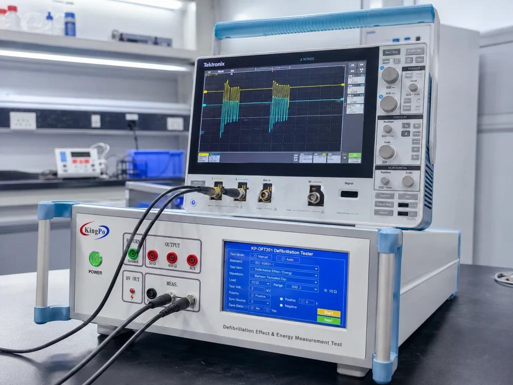
The touchscreen shown in the actual delivery photograph includes a GB 9706.1-2020 / IEC 60601-1:2020 selection. This confirms that the interface contains a standard-related configuration menu, but it does not mean that one test circuit or acceptance criterion applies to every medical electrical device.
General medical electrical safety requirements may be supplemented by particular standards for electrocardiographs, patient monitors or other patient-connected equipment. Particular standards can modify the applied-part configuration, pulse sequence, test circuit, operating state, recovery period and acceptance criteria.
Laboratories planning broader capability can review KingPo’s IEC 60601-1 test equipment list and range of medical electrical safety test equipment for related leakage-current, electrosurgical, ECG, defibrillation and other medical-device test applications.
| Standard Context | Application Boundary |
|---|---|
| IEC 60601-1 / GB 9706.1 | General medical electrical safety requirements, including protection against defibrillation effects where applicable |
| ECG-related particular standards | Additional requirements for electrocardiographs, patient monitors, ECG monitoring equipment and associated patient connections |
| Other particular standards | Product-specific requirements may define different circuits, operating conditions, pulse sequences, recovery times and acceptance limits |
Do not configure the test from voltage alone
A valid defibrillation-effect test requires the specified waveform, circuit impedance, polarity, pulse sequence, connection mode, specimen operating state, measurement method and post-test assessment. Matching only the peak voltage is insufficient.
Laboratory Preparation and Safety Considerations
The KP-DFT201 is used in a high-voltage transient test environment. The laboratory should establish a controlled operating area, approved wiring diagrams and a repeatable connection procedure before routine testing begins.
Controlled test area
The tester, oscilloscope and equipment under test should be positioned so that operators can view the interfaces without reaching across energized leads. Unrelated personnel should be kept outside the test area during pulse application.
Connection verification
Output, return and measurement leads should be checked against the approved test diagram before the high-voltage output is enabled. Connections should not be changed while stored energy may remain in the circuit.
Grounding and measurement isolation
The grounding arrangement of the tester, oscilloscope and equipment under test must be reviewed as a complete system. An incorrect ground connection can change the intended pulse path or create an unsafe condition.
Discharge and waiting procedure
The laboratory should define how stored energy is discharged and how the operator confirms a safe state before disconnecting the equipment under test or moving measurement leads.
Documentation, Verification and Calibration Planning
Before the tester enters routine use, the laboratory should define the documentation required by its quality system. Relevant records may include operating instructions, wiring diagrams, approved test methods, equipment identification, connection photographs, oscilloscope setup records, maintenance instructions and software or configuration records.
Verification and calibration should be planned by measurement parameter rather than by the product name alone. The tester and oscilloscope form part of one measurement chain, and each relevant parameter should be linked to the laboratory’s traceability and recalibration plan.
Depending on the applicable method, the scope may need to include:
- High-voltage output magnitude and polarity
- Pulse waveform and timing characteristics
- Resistance and inductance values in the selected test circuit
- Pulse count and interval timing
- Energy measurement or energy-calculation method
- Oscilloscope input scaling and external attenuation ratio
- Measurement-channel bandwidth and timing accuracy
- Residual-voltage measurement function where applicable
- Software, test-sequence and connection-state verification where required
Project evidence boundary
The supplied photographs confirm the delivered model, front-panel configuration, laboratory setup and waveform-observation arrangement. They do not by themselves establish calibration status, measurement uncertainty, formal customer acceptance or a test pass/fail result.
Practical Value for a Medical Electrical Safety Laboratory
A touchscreen-controlled system can reduce repetitive manual switching and improve consistency between test sequences. However, the value of automation depends on correct circuit selection, verified wiring and a documented measurement process.
Dedicated output and measurement terminals also make the setup easier to inspect. Operators can identify the high-voltage path, return path and oscilloscope connections without relying on temporary external wiring for every routine test.
For laboratories testing different categories of patient-connected equipment, the main advantage is configurability. The tester can be reviewed against the laboratory’s applicable standards, test circuits, lead arrangements and documentation requirements instead of being selected only by a headline voltage specification.
Engineering Notes for Similar Laboratories
Confirm the exact standard and clause
The phrase “defibrillation test” is not enough to define a configuration. The laboratory should identify the general standard, particular standard, edition, clause, device type and patient connection arrangement before selecting the pulse circuit.
Verify the complete measurement chain
The tester, oscilloscope, probes, cables, attenuation devices, circuit components and grounding arrangement all influence the recorded waveform. Verification should cover the same configuration used during routine testing.
Separate waveform review from conformity assessment
A visible waveform is useful for confirming setup and signal behaviour, but conformity must be based on the specified measurement method, numerical limits, operating condition and post-test performance criteria.
Record every configurable parameter
Voltage, polarity, pulse count, interval, selected output, measurement channel, oscilloscope range and specimen operating mode should be recorded so that the test can be repeated and independently reviewed.
Define the post-test assessment before exposure
The laboratory should not decide after the pulse which functions to inspect. Residual voltage, recovery time, alarms, displayed values, essential performance and other required checks should be specified in the test plan before exposure.
Information Required for a Similar Test System
To configure a similar defibrillation effect and energy measurement system, the laboratory should provide:
- Applicable IEC 60601, GB 9706 or particular-standard references and editions
- Type of medical electrical equipment being tested
- Applied-part classification and patient connection arrangement
- Required common-mode and differential-mode test circuits
- Required waveform, voltage and polarity
- Required resistance and inductance values
- Pulse count, pulse interval and operating sequence
- Energy-reduction and residual-voltage requirements
- Number of measurement channels and oscilloscope configuration
- Manual or automatic lead-switching requirements
- Required test reports, calibration points and certificate type
- Laboratory power supply, bench layout and high-voltage safety requirements
Frequently Asked Questions
Planning a Defibrillation Effect or Energy Measurement Test?
Send KingPo the applicable IEC 60601 or GB 9706 clauses, medical equipment type, patient connections, required pulse circuits, waveform conditions, oscilloscope setup and calibration requirements. The tester and accessory configuration can then be reviewed against the laboratory’s actual workflow.