Abstract
IEC 62368-1 impulse testing is sometimes reduced to two parameters: test voltage and waveform. In practice, the suitability of an impulse test generator also depends on the generator network, applicable test circuit, source characteristics and the electrical behavior of the device under test (DUT). This article reviews the practical differences between the 10/700 μs and 1.2/50 μs impulse conditions used in IEC 62368-1, explains the role of the Annex D test circuits, and discusses why the measured waveform can change when a real DUT is connected. Particular attention is given to the distinction between IEC 62368-1 impulse testing and IEC 61000-4-5 surge immunity testing.
Introduction
Impulse testing appears simple when it is described only in terms of peak voltage. A laboratory sets the required voltage, applies several impulses and observes the DUT. This description is adequate for a general overview, but it leaves out the part that often determines whether the test setup is technically correct: the electrical characteristics of the generator itself.
Two impulse generators can reach the same peak voltage and still behave differently when connected to the same DUT. Similarly, two instruments may both specify a 1.2/50 μs waveform without being intended for the same test standard.
For IEC 62368-1, it is therefore more useful to treat the generator as part of a defined test circuit, rather than as an isolated high-voltage source.
The main points examined below are the waveform definition, the Annex D generator circuits, the influence of DUT impedance, and the relationship between IEC 62368-1 impulse testing and IEC 61000-4-5 surge testing.
Technical Basis of an Impulse Test Generator
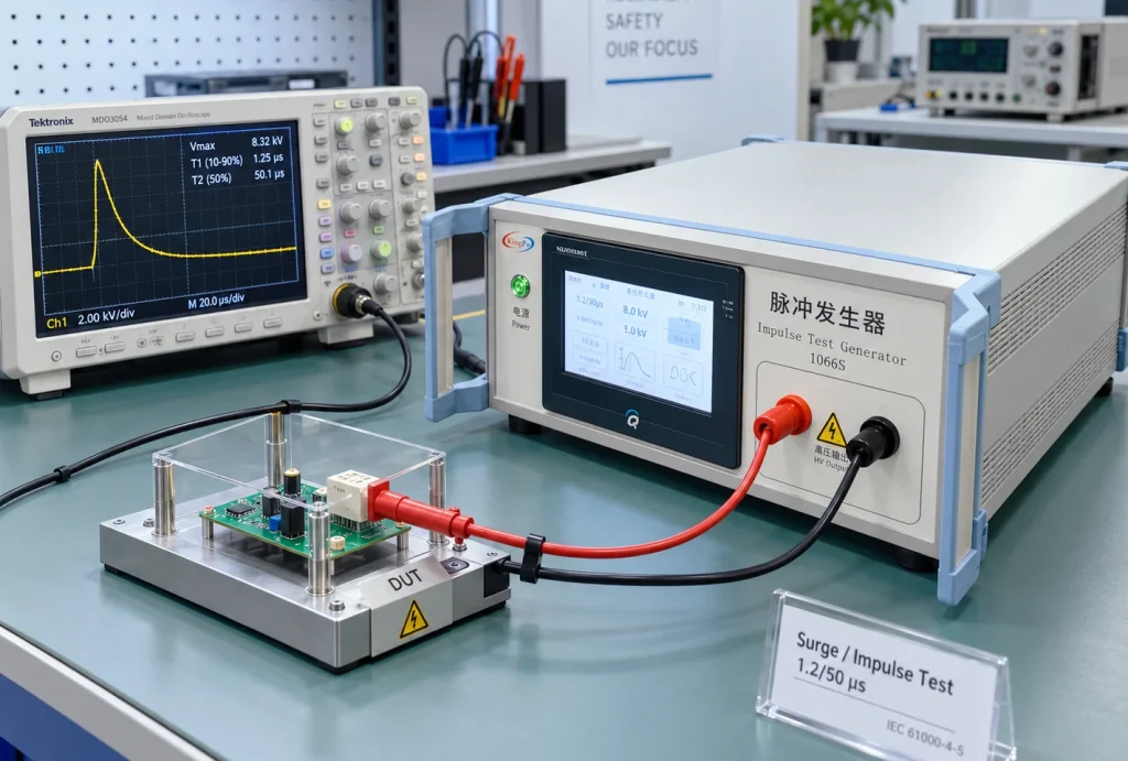
An impulse test generator produces a short-duration high-voltage transient with defined electrical characteristics. The output waveform is formed by a network of resistance, capacitance, stored energy and switching elements.
The resulting impulse is therefore affected by more than the charging voltage. Source impedance, pulse-forming components and the connected load all contribute to the voltage and current that appear at the DUT terminals.
This distinction becomes important when the DUT contains nonlinear protection components. A MOV, TVS diode or gas-discharge tube may present a relatively high impedance below its operating threshold and a much lower impedance once it begins to conduct.
In that condition, the generator is no longer operating into an essentially open circuit. Its source characteristics become part of the test result.
For this reason, a specification such as “6 kV impulse generator” is incomplete for laboratory use. A more useful description identifies the standard, test circuit and waveform, for example:
IEC 62368-1 Table D.1, Circuit 1, 10/700 μs
Characteristics of the 10/700 μs and 1.2/50 μs Waveforms
The two impulse-voltage descriptions most frequently encountered in IEC 62368-1 are 10/700 μs and 1.2/50 μs.
These values describe the time characteristics of the impulse. They should not be interpreted simply as pulse duration. A standardized impulse rises to a peak and then decays, and its timing is evaluated using defined waveform parameters.
10/700 μs Impulse
The 10/700 μs impulse has a relatively slow front and a long decay. It is associated with specified transient conditions for certain external and communication circuits.
The longer tail means that the DUT can be subjected to a different energy and current condition from that produced by a faster impulse, even when the peak voltage is similar.
1.2/50 μs Impulse
The 1.2/50 μs waveform has a much faster front and shorter decay. It is widely used in transient-voltage and insulation-related testing.
However, the notation “1.2/50 μs” does not fully define the electrical source. Different standards can use the same nominal voltage waveform with different source networks and different test objectives.
Selection of the IEC 62368-1 Test Circuit
A common simplification is to associate a communication port directly with 10/700 μs and a power circuit directly with 1.2/50 μs. This is useful as a general explanation but should not be used as the sole basis for a test plan.
The applicable transient condition depends on the relevant edition of IEC 62368-1, the classification of the external circuit and the expected installation environment.
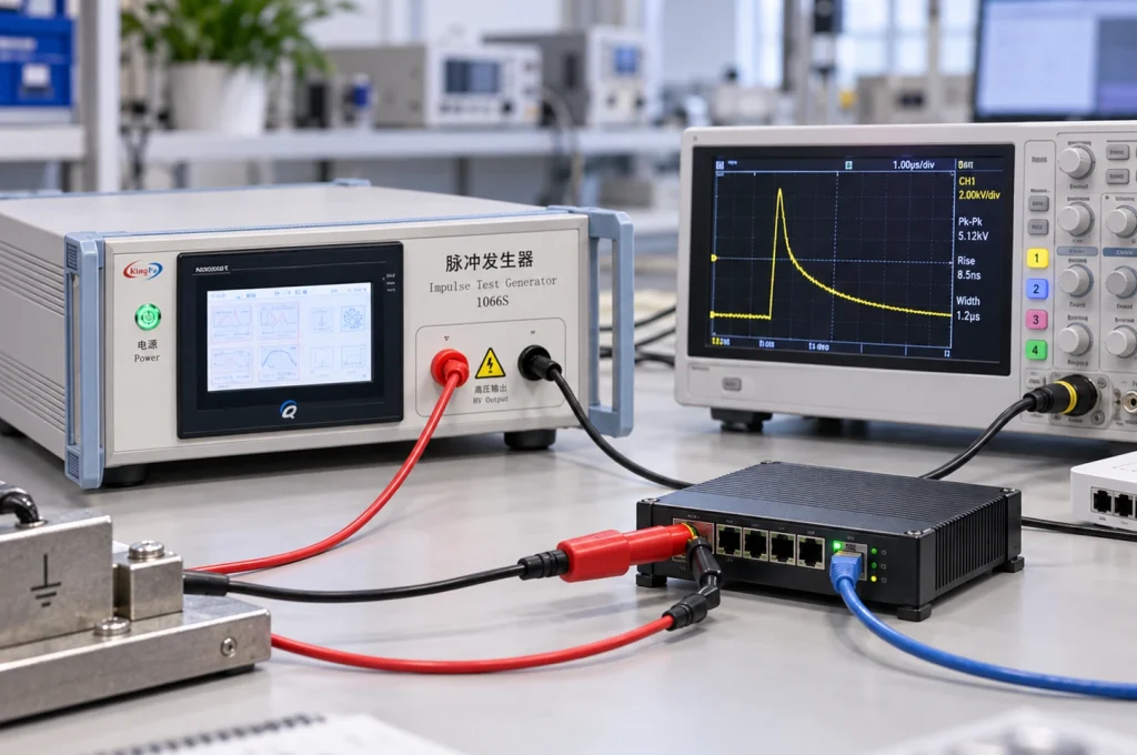
Ethernet provides a useful example. Two Ethernet interfaces may use the same physical connector, while one is associated with an outdoor-exposed network and the other remains entirely within a building. Their expected transient conditions need not be identical.
A practical test-planning sequence is therefore:
- identify the applicable IEC 62368-1 edition or national adoption;
- identify the DUT interface and installation condition;
- locate the relevant clause, annex, figure or table;
- determine the specified test circuit;
- confirm waveform, polarity and test voltage;
- select the corresponding generator configuration.
IEC 62368-1 Annex D Generator Circuits
IEC 62368-1 Annex D does not define one universal impulse generator. Table D.1 identifies several generator configurations.
| Circuit | Waveform / Arrangement | Reference |
|---|---|---|
| Circuit 1 | 10/700 μs | Figure D.1 / Table D.1 |
| Circuit 2 | 1.2/50 μs | Figure D.1 / Table D.1 |
| Circuit 3 | Separate generator arrangement | Figure D.2 / Table D.1 |
Circuits 1 and 2 use different pulse-forming networks. They can be incorporated into one instrument if the required networks can be selected independently.
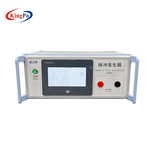
The KP-1950S IEC 62368-1 impulse test generator provides the 10/700 μs and 1.2/50 μs configurations used for Table D.1 Circuit 1 and Circuit 2.
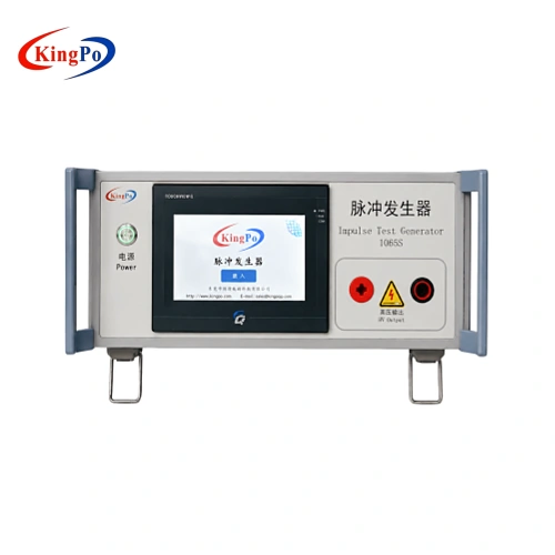
Where Figure D.2 / Circuit 3 applies, the KP-1065S Figure D.2 pulse voltage generator uses the corresponding circuit arrangement.
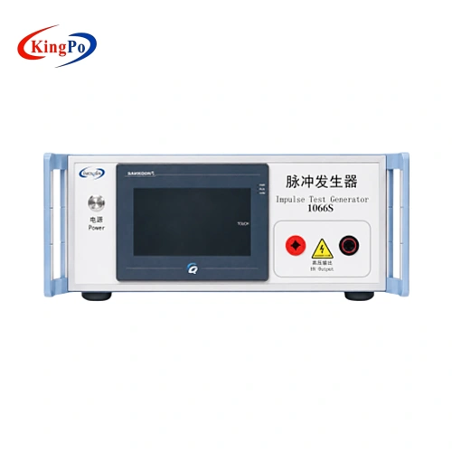
Annex D also contains a separate electronic pulse generator configuration , represented by the KP-1066S.
Comparison With IEC 61000-4-5 Surge Testing
The presence of a 1.2/50 μs waveform in IEC 62368-1 sometimes leads to the assumption that an IEC 61000-4-5 surge generator can be used interchangeably.
The similarity is real, but incomplete.
A typical IEC 61000-4-5 combination-wave generator is characterized by a 1.2/50 μs open-circuit voltage and an 8/20 μs short-circuit current. Its source impedance and coupling arrangement are part of the EMC immunity test method.
IEC 62368-1 Circuit 2 uses a 1.2/50 μs voltage impulse but specifies its own generator network. The waveform notation is therefore not sufficient to establish equivalence between the two sources.
| Parameter | IEC 62368-1 | IEC 61000-4-5 |
|---|---|---|
| Primary purpose | Safety / transient withstand | EMC surge immunity |
| Voltage waveform | Depends on applicable circuit | 1.2/50 μs open circuit |
| Current characteristic | Defined by the selected IEC 62368-1 circuit | 8/20 μs short circuit |
| Interchangeable by waveform name? | No | No |
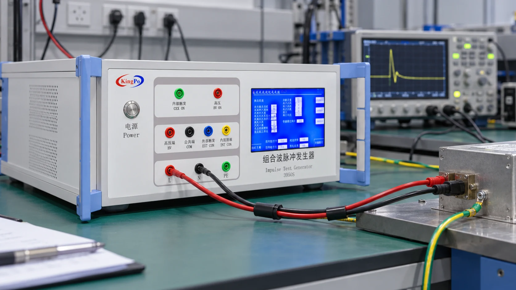
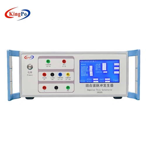
The KP-3950S IEC 61000-4-5 combination wave surge generator illustrates this distinction. Its output is intended for the IEC 61000-4-5 combination-wave test, rather than simply for any test in which the term “1.2/50 μs” appears.
Influence of DUT Loading on the Impulse Waveform
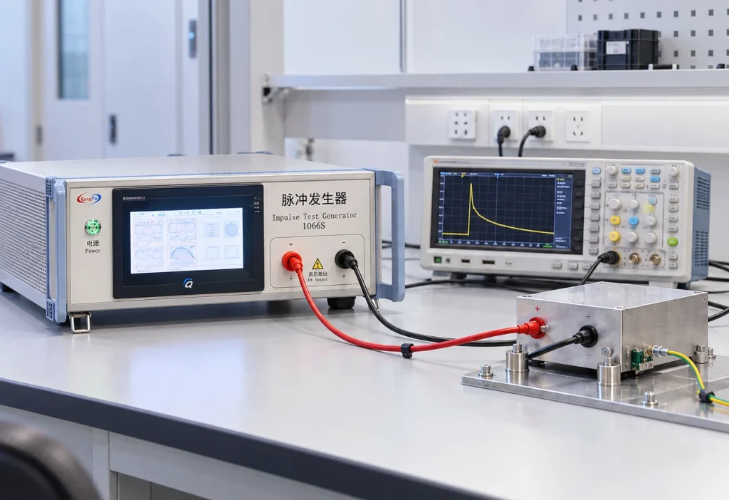
Generator verification and testing with the DUT connected are two different electrical conditions.
During generator verification, the waveform is measured under the condition specified for the generator. Once the DUT is connected, its impedance becomes part of the circuit.
A real electronic product may include MOVs, TVS diodes, gas-discharge tubes, transformers, filters, capacitors and semiconductor junctions. Several of these components have strongly nonlinear voltage-current characteristics.
A TVS diode, for example, can have little effect below its clamping voltage. Once conduction starts, its impedance falls and the load on the generator increases rapidly. The voltage trace can then appear clipped or reduced.
A gas-discharge tube can produce an even more abrupt change when it fires.
Typical changes observed after the DUT is connected include:
- reduction of the measured peak voltage;
- shortening of the waveform tail;
- voltage clamping;
- rapid voltage collapse after a protection device operates;
- ringing or oscillation around the peak.
These effects do not by themselves indicate that the impulse generator is out of calibration. They may simply reflect the interaction between the generator network and the DUT.
Measurement and Waveform Verification
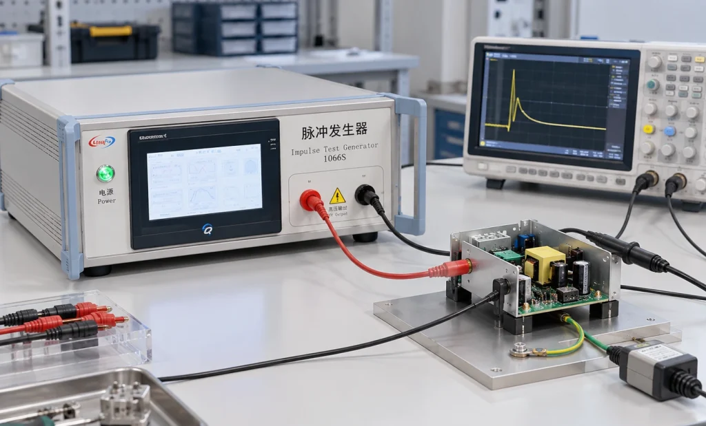
When the oscilloscope trace does not agree with the generator setting, the measurement chain should be checked before the generator is adjusted.
Relevant points include:
- whether the generator display represents a programmed or measured value;
- the monitoring-divider ratio;
- high-voltage probe attenuation;
- oscilloscope input scaling;
- measurement bandwidth;
- grounding and cable arrangement;
- whether the DUT is connected during the measurement.
The KP-1950S, for example, provides a nominal 1:1000 monitoring output. This simplifies waveform observation, but the oscilloscope and measurement configuration still need to be interpreted correctly.
Discussion
Several practical conclusions follow from the circuit analysis above.
First, maximum output voltage should not be used as the primary selection criterion for an IEC 62368-1 impulse test generator. It establishes whether the required voltage is available, but it does not establish whether the required test circuit is reproduced.
Second, a waveform designation such as 1.2/50 μs should not be treated as a complete generator specification. The source network and intended standard remain relevant.
Third, waveform changes after connection of the DUT need to be interpreted in the context of DUT impedance and protection-component operation. A loaded waveform should not automatically be compared with an open-circuit verification waveform as though both measurements represented the same condition.
Finally, functional survival alone is not a universal pass criterion. The applicable IEC 62368-1 requirement determines whether insulation breakdown, safeguard degradation, flashover or other effects are acceptable.
Information Required for Equipment Selection
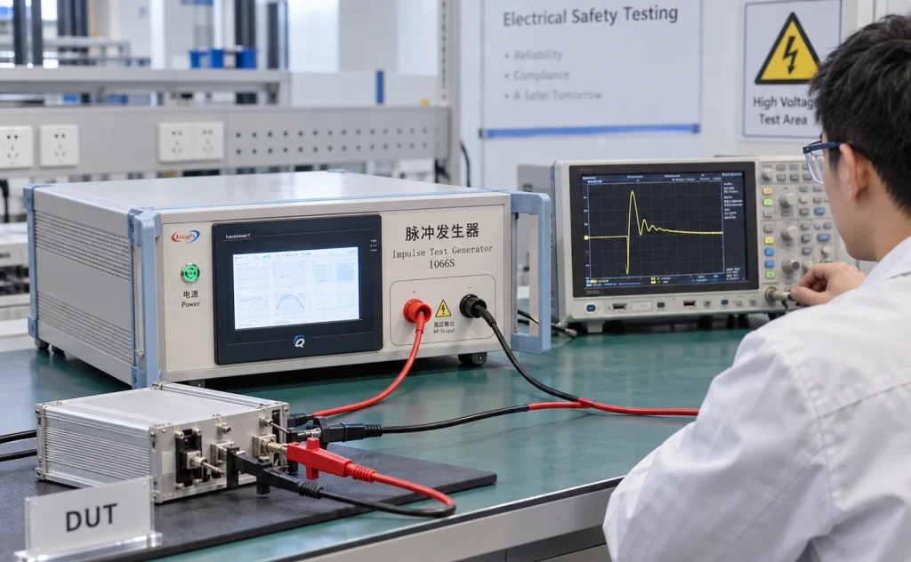
A laboratory or purchaser does not need to provide a complete test report when requesting equipment, but the following information significantly reduces the risk of selecting the wrong generator.
| Item | Required Information |
|---|---|
| Standard | IEC 62368-1 and applicable edition |
| Reference | Clause, Annex, Figure or Table |
| Test circuit | Circuit 1, Circuit 2, Circuit 3 or other specified configuration |
| Waveform | 10/700 μs, 1.2/50 μs or other required condition |
| Voltage | Normal test level and maximum required level |
| DUT / interface | Power, Ethernet, antenna, communication circuit, etc. |
| Other requirements | Polarity, pulse interval, monitoring and calibration |
Where the exact generator circuit is not known, providing the DUT type, interface and applicable standard clause is generally more useful than providing the voltage alone.
A more detailed discussion of generator selection is available in Beyond Peak Voltage: How to Select the Right Impulse Test Generator for IEC 62368-1 .
Generator Configurations for Related Tests
The following equipment mapping is included only to show the relationship between the standard reference and the generator configuration.
| Model | Standard Reference | Configuration |
|---|---|---|
| KP-1950S | IEC 62368-1 Table D.1 Circuit 1 / Circuit 2 | 10/700 μs and 1.2/50 μs |
| KP-1065S | IEC 62368-1 Figure D.2 / Circuit 3 | Dedicated Circuit 3 arrangement |
| KP-1066S | IEC 62368-1 Annex D.3 | Electronic pulse generator |
| KP-3950S | IEC 61000-4-5 | 1.2/50 μs voltage / 8/20 μs current |
Conclusion
IEC 62368-1 impulse testing cannot be defined adequately by peak voltage alone. The waveform and the generator network both determine the electrical stress applied to the DUT.
The distinction becomes particularly important when comparing 10/700 μs and 1.2/50 μs generators, when comparing IEC 62368-1 with IEC 61000-4-5, and when interpreting a waveform after nonlinear protection components begin to conduct.
In practical laboratory work, the most reliable approach is to identify the applicable standard edition and test circuit first, verify the required waveform and voltage second, and select the impulse generator only after those conditions are known.
This reduces ambiguity during equipment selection and provides a clearer basis for interpreting waveform behavior during the actual test.
Related IEC 62368-1 instruments and test methods are listed in the IEC 62368-1 test equipment guide .
References
- IEC 62368-1, Audio/video, information and communication technology equipment — Safety requirements.
- IEC 61000-4-5, Electromagnetic compatibility (EMC) — Testing and measurement techniques — Surge immunity test.
- ITU-T Recommendation K.44, Resistibility tests for telecommunication equipment exposed to overvoltages and overcurrents.