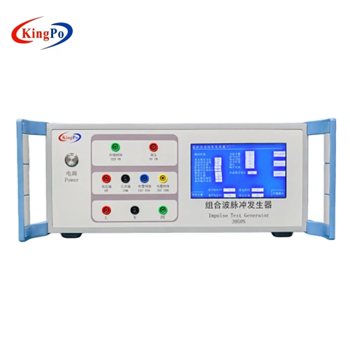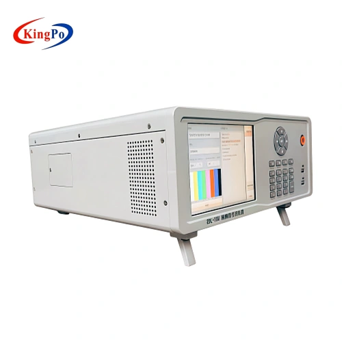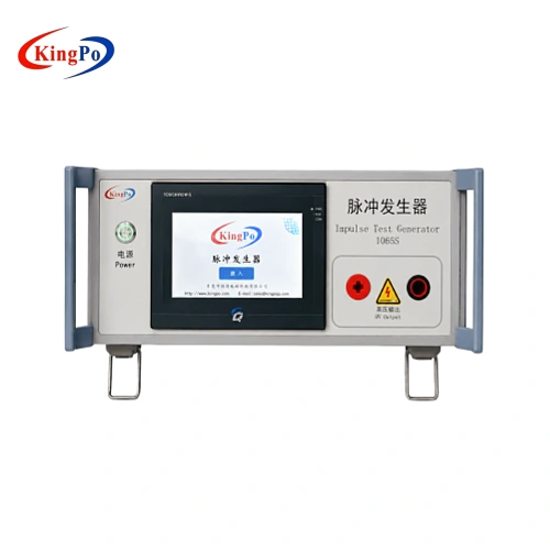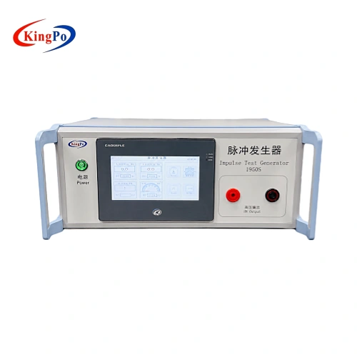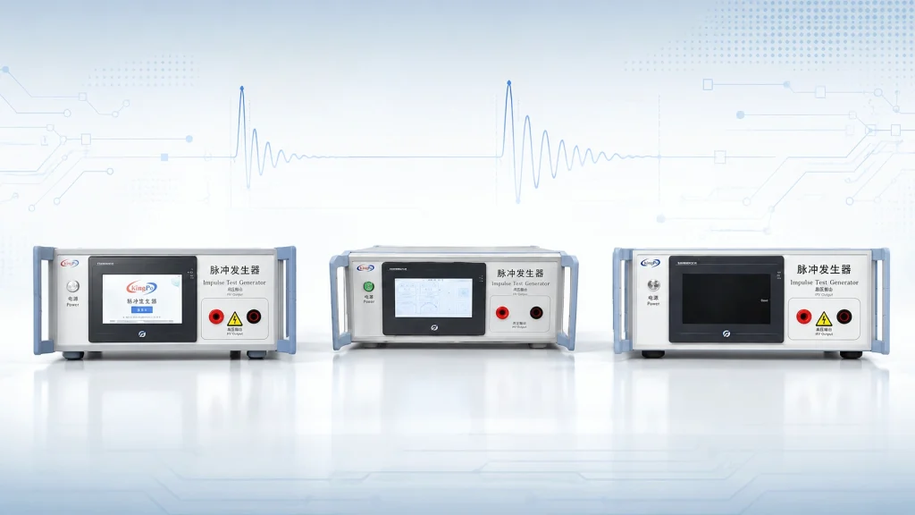
A typical request for quotation may contain only one sentence:
“We need a 5 kV impulse test generator for IEC 62368-1.”
That information is not sufficient for reliable equipment selection.
Several generators may cover a similar voltage range while using different capacitance values, resistance networks, source characteristics, discharge methods and test connections. They may also correspond to different figures or circuits within IEC 62368-1.
The correct impulse test generator must therefore be selected according to the applicable standard edition, circuit reference, required waveform, device-under-test (DUT) interface and measurement method—not simply by the maximum kilovolt rating.
The IEC currently lists IEC 62368-1:2023 as Edition 4.0 of the safety standard for audio/video, information and communication technology equipment. A certification project may still reference a national adoption or another edition, so the applicable edition must be recorded before equipment is selected.
Engineering answer:
Select the required IEC 62368-1 circuit first, confirm the waveform or discharge configuration second, and check the voltage range third.
Scope: this guide covers compact impulse and pulse-voltage generators used for IEC 62368-1 AV/ICT product-safety testing. It does not cover large multi-stage impulse systems used for transformers, power cables, GIS or utility-class high-voltage testing.
What Does an Impulse Test Generator Do?
An impulse test generator applies a controlled, short-duration high-voltage stress to a product, interface or insulation system.
Depending on the applicable test circuit, the generator may be used to assess:
- insulation withstand performance;
- breakdown or flashover risk;
- the behavior of protective components;
- the withstand capability of communication or antenna interfaces;
- abnormal operation after transient electrical stress;
- design margins before formal certification testing.
Customers may also search for this category of equipment using terms such as impulse voltage generator or pulse voltage generator. These names can overlap in commercial searches, but the product name alone does not determine technical suitability.
The decisive information is the circuit and test condition required by the standard.
Why Maximum Voltage Is Not Enough
The maximum output voltage is only one boundary of an impulse generator.
It does not define:
- the stored electrical energy;
- the impulse waveform;
- the effective source impedance;
- the rise and decay characteristics;
- the capacitance and resistance network;
- the polarity sequence;
- the DUT connection;
- the test repetition interval;
- the required measurement method.
This is particularly important when two generators have similar voltage ratings but very different capacitance values.
The ideal energy stored in a capacitor before discharge is:
For example:
- A 1 nF capacitor charged to 10 kV stores approximately 0.05 J.
- A 0.42 μF capacitor charged to 3 kV stores approximately 1.89 J.
The second circuit stores approximately 38 times as much ideal capacitor energy despite operating at less than one-third of the voltage.
This calculation does not represent the exact energy delivered to the DUT. Actual delivered energy depends on the complete resistance network, switching circuit, parasitic elements and DUT impedance. It nevertheless demonstrates why selecting an impulse test generator by kV alone is technically unsound.
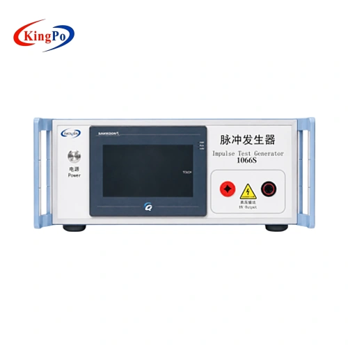
The KP-1065S uses a nominal 1 nF/30 kV capacitance, while the KP-1066S Annex D.3 generator uses a nominal 0.42 μF capacitance. Their overlapping voltage ranges do not make them interchangeable.
Start With the Exact IEC 62368-1 Reference
Before comparing equipment specifications, identify the applicable standard reference.
A complete test requirement should normally identify some combination of:
- applicable standard and edition;
- clause, annex or figure;
- Table D.1 circuit number;
- required impulse waveform;
- test voltage;
- DUT port or interface;
- polarity;
- number of applications;
- interval between applications;
- monitoring and calibration requirements.
“IEC 62368-1 impulse test” is too broad because Annex D contains more than one generator configuration.
The three KingPo models discussed below are not simply low-, medium- and high-voltage versions of the same instrument. They represent different circuit requirements.
IEC 62368-1 Generator Selection at a Glance
| Model | Standard reference | Principal configuration | Output range | Primary selection condition |
|---|---|---|---|---|
| KP-1950S | Figure D.1 / Table D.1 Circuit 1 and Circuit 2 | 10/700 μs and 1.2/50 μs impulse waveforms | 0–4 kV / 0–6 kV | The test plan specifies Circuit 1, Circuit 2 or either defined waveform |
| KP-1065S | Annex D, Figure D.2 / Table D.1 Circuit 3 | 1 nF antenna-interface test generator circuit | 0–10 kV | The test plan specifies Figure D.2 and Table D.1 Circuit 3 |
| KP-1066S | Annex D.3 / Figure D.3 | Electronic pulse generator circuit with 0.42 μF capacitance | 0.5–3 kV | The test plan specifies the Annex D.3 electronic pulse generator |
KP-1950S for 10/700 μs and 1.2/50 μs Impulse Testing
The IEC 62368-1 Table D.1 Impulse Test Generator KP-1950S is intended for projects requiring the Figure D.1-related impulse circuits.
It provides:
- 10/700 μs output from 0 to 4 kV;
- 1.2/50 μs output from 0 to 6 kV;
- Table D.1 Circuit 1 and Circuit 2 configurations;
- positive and negative alternating polarity;
- programmable charge/discharge timing;
- programmable test cycles;
- a nominal 1:1000 monitoring output.
The 10/700 μs waveform is typically associated with transient conditions on communication networks, while the 1.2/50 μs waveform is commonly associated with transient voltage conditions related to distribution systems. The applicable circuit must still be determined from the product test plan rather than from these general descriptions alone.
Select KP-1950S when:
- the test plan identifies Table D.1 Circuit 1 or Circuit 2;
- a 10/700 μs impulse is required;
- a 1.2/50 μs impulse is required;
- both waveforms must be available in one system;
- positive and negative impulse applications are required;
- oscilloscope waveform observation is part of the laboratory procedure.
Do not select it merely because its 6 kV range covers the voltage written in the RFQ.
KP-1065S for Figure D.2 and Table D.1 Circuit 3
The IEC 62368-1 Figure D.2 Pulse Voltage Generator KP-1065S corresponds to the antenna-interface test generator circuit and Table D.1 Circuit 3.
Its current technical configuration includes:
- adjustable output from 0 to 10 kV;
- 0.01 kV setting resolution;
- 1 nF/30 kV charging capacitance;
- programmable charging and discharge timing;
- programmable test count;
- a nominal 1:1000 oscilloscope monitoring output;
- PLC and touchscreen control.
It is intended primarily for antenna interfaces and communication-related ports in AV/ICT equipment.
This equipment is often found through the search term pulse voltage generator, but the search term should not replace the formal circuit reference during technical selection.
Select KP-1065S when:
- the test requirement explicitly identifies Figure D.2;
- Table D.1 Circuit 3 is specified;
- the DUT has an antenna, coaxial or relevant communication interface;
- the 1 nF circuit configuration is required;
- the project requires up to 10 kV under the Figure D.2 circuit condition.
A request for an “IEC 62368-1 10 kV generator” is still incomplete unless the Figure D.2 and Circuit 3 requirement is confirmed.
KP-1066S for the Annex D.3 Electronic Pulse Circuit
The IEC 62368-1 Annex D.3 Impulse Test Generator KP-1066S is a separate electronic pulse generator configuration.
Its current specifications include:
- 0.5 to 3 kV adjustable output;
- 0.01 kV resolution;
- 0.42 μF capacitance;
- 1 to 99 seconds adjustable discharge time;
- 1 to 999 programmable test cycles;
- PLC and touchscreen control.
The KP-1066S is intended for projects whose test plan explicitly calls for the Annex D.3 electronic pulse generator circuit. The DUT type and connection arrangement should be confirmed against the applicable standard edition and laboratory procedure.
Select KP-1066S when:
- Annex D.3 or Figure D.3 is identified in the test plan;
- the electronic pulse generator circuit is required;
- the specified 0.42 μF circuit configuration is relevant;
- the required voltage falls within 0.5 to 3 kV;
- repeatable charge and discharge applications are required.
The KP-1066S is not a lower-voltage version of the KP-1065S or KP-1950S. Its capacitance, energy storage and discharge behavior are fundamentally different.
Common Problem 1: The RFQ Contains Only a Standard and Voltage
A customer may request:
“Please quote an IEC 62368-1 impulse test generator, 5 kV.”
At least three critical facts are missing:
- Which figure or circuit applies?
- What waveform or discharge network is required?
- Which DUT interface will be tested?
Five kilovolts falls within the operating range of multiple models, but those models perform different tests.
The appropriate response is not to select the nearest voltage range. The supplier should request the test clause, figure, circuit diagram or certification test plan before issuing a technically binding configuration.
Common Problem 2: Open-Circuit Output Changes After Connecting the DUT
An impulse generator may show the expected voltage or waveform during reference verification, but the result can change when the DUT is connected.
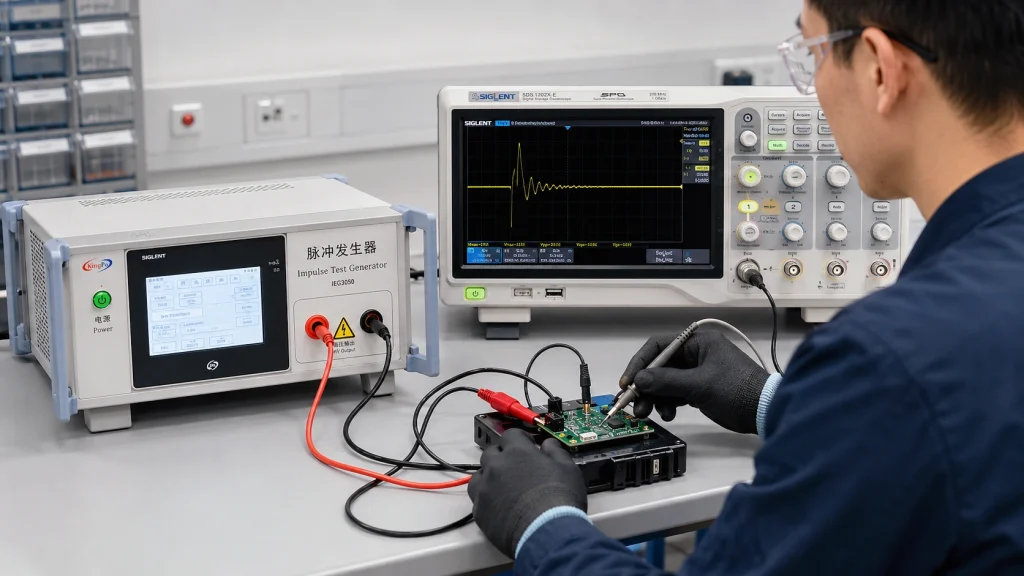
Possible observations include:
- lower peak voltage;
- slower front time;
- altered decay time;
- overshoot or ringing;
- asymmetry between positive and negative polarity;
- unexpected operation of a surge-protective component;
- premature breakdown or flashover.
This does not automatically prove that the generator is defective.
The DUT adds impedance, capacitance, protective devices and parasitic elements to the discharge path. Test lead length, grounding and connection geometry can also affect the measured result.
Practical troubleshooting sequence
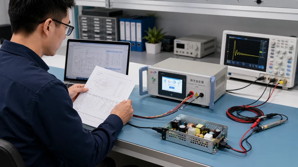
First verify the generator using the laboratory’s approved reference arrangement. Then connect the DUT without changing the measurement configuration unnecessarily.
If the result changes:
- confirm the correct generator circuit;
- check the DUT connection point;
- shorten high-voltage and return paths;
- inspect grounding and loop area;
- confirm the oscilloscope and divider settings;
- determine whether a protection component is conducting;
- compare positive and negative polarity results;
- document both the reference and loaded waveforms.
Whether the waveform must be evaluated under open-circuit, reference-load or DUT-connected conditions depends on the applicable test requirement and approved laboratory procedure.
Common Problem 3: The Generator Display and Oscilloscope Do Not Agree
A monitoring output makes waveform observation easier, but it does not eliminate measurement error.
Both the KP-1950S and KP-1065S specify a nominal 1:1000 monitoring ratio.
Before interpreting a waveform, verify:
- the calibrated monitoring ratio;
- oscilloscope channel attenuation;
- probe or divider settings;
- input impedance;
- bandwidth;
- sample rate;
- trigger level and polarity;
- vertical range;
- measurement grounding;
- whether the displayed value is measured at the monitoring port or DUT terminal.
For example, a nominal 1 V monitoring signal may represent approximately 1 kV at a 1:1000 ratio. The actual conversion must follow the calibrated ratio and measurement documentation, not a nominal assumption.
A technically complete test record should include:
- generator model and serial number;
- selected circuit;
- voltage setting;
- waveform;
- polarity;
- test count;
- charging and discharge interval;
- oscilloscope model;
- channel attenuation;
- calibrated divider ratio;
- DUT operating state;
- saved waveform data or screenshots.
Common Problem 4: Using an EMC Surge Generator as a Substitute
Customers frequently ask whether an existing IEC 61000-4-5 surge generator can be used for IEC 62368-1 testing.
The instruments should not be treated as automatically interchangeable.
IEC 61000-4-5 addresses EMC surge immunity, while IEC 62368-1 is a product-safety standard. Even when similar waveform terminology appears, the generator circuit, source characteristics, coupling arrangement, test port and acceptance objective may be different.
Before substituting any generator, compare:
- circuit topology;
- generator capacitance;
- resistance values;
- source impedance;
- voltage waveform;
- current waveform;
- coupling/decoupling method;
- output polarity;
- test port;
- test objective;
- verification and calibration requirements.
The fact that two instruments can both produce a 1.2/50 μs or 10/700 μs-related output does not prove that their complete circuits and test methods are equivalent.
A substitution should only be accepted after the responsible laboratory or certification body verifies that the equipment reproduces the required IEC 62368-1 test condition.
Common Problem 5: “Calibration Certificate Required” Is Too Vague
A purchasing specification may state only:
“Calibration certificate must be supplied.”
That wording does not define what must be measured.
The laboratory should determine whether the documentation must cover:
- output voltage at specified test points;
- positive and negative polarity;
- 1.2/50 μs time parameters;
- 10/700 μs time parameters;
- monitoring-output divider ratio;
- voltage display accuracy;
- capacitance;
- charging or discharge timing;
- test-count accuracy;
- measurement uncertainty;
- traceability;
- the applicable report language;
- ISO/IEC 17025 accreditation requirements.
A calibration report that covers only voltage display accuracy may not satisfy a laboratory expecting waveform verification and monitoring-ratio measurement.
The calibration scope, measurement points and issuing laboratory should therefore be agreed before the purchase order is released.
Common Problem 6: The Generator Applies the Pulse, but Pass/Fail Criteria Are Unclear
An impulse test generator applies the specified electrical stress. It does not independently determine whether the DUT complies with every requirement.
During and after testing, engineers may need to observe:
- insulation breakdown;
- flashover or arcing;
- protective component failure;
- abnormal shutdown or reset;
- permanent functional damage;
- loss of a required safeguard;
- deterioration of insulation;
- unacceptable deformation or overheating;
- normal recovery after the test;
- post-test dielectric or functional results.
The final acceptance criteria must come from the applicable standard clause, certification plan and laboratory procedure.
A “test completed” indication on the generator does not by itself mean that the product passed.
A Practical Selection Workflow
Step 1: Confirm the standard edition
Record the exact IEC, EN, UL, CSA, GB or other national adoption used by the project.
Do not assume that every market is applying the same edition at the same time.
Step 2: Identify the exact reference
Request the clause, annex, figure and Table D.1 circuit number.
When the customer is uncertain, ask for the relevant page of the test plan or a circuit diagram.
Step 3: Confirm the DUT interface
Determine whether the test is applied to:
- a mains-related circuit;
- a communication port;
- a network interface;
- an antenna or coaxial interface;
- a power adapter;
- an internal circuit;
- another accessible or external connection.
Step 4: Confirm the waveform or circuit configuration
Do not use the generic phrase “surge test” as the only requirement.
Record whether the project requires:
- 10/700 μs;
- 1.2/50 μs;
- Figure D.2 / Circuit 3;
- the Annex D.3 electronic pulse circuit;
- another explicitly defined condition.
Step 5: Check more than voltage
Verify:
- output range;
- capacitance;
- resistance network;
- polarity;
- test interval;
- number of tests;
- monitoring output;
- control and recording functions.
Step 6: Define the measurement system
Confirm whether the laboratory will use:
- the built-in monitoring output;
- an external high-voltage divider;
- a storage oscilloscope;
- automated data capture;
- open-circuit verification;
- loaded waveform verification.
Step 7: Define the documentation scope
Agree on the datasheet, circuit confirmation, inspection report, calibration report, measurement points and traceability requirements before ordering.
Impulse Test Generator Selection Matrix
| Customer requirement | Recommended direction |
|---|---|
| Table D.1 Circuit 1 | KP-1950S |
| 10/700 μs impulse waveform | KP-1950S |
| Table D.1 Circuit 2 | KP-1950S |
| 1.2/50 μs impulse waveform | KP-1950S |
| Figure D.2 / Table D.1 Circuit 3 | KP-1065S |
| Antenna-interface test generator circuit | KP-1065S |
| 1 nF configuration with up to 10 kV output | KP-1065S |
| Annex D.3 / Figure D.3 | KP-1066S |
| 0.42 μF electronic pulse generator circuit | KP-1066S |
| Customer specifies only “5 kV” | More information required |
| Customer specifies only “surge generator” | Standard, circuit and waveform must be confirmed |
| Customer wants to reuse an IEC 61000-4-5 generator | Full technical equivalence must be evaluated |
Information Required Before Quotation
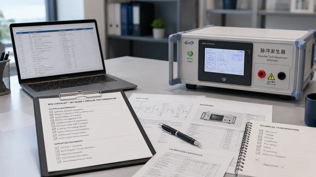
A technically useful RFQ should include the following:
- Applicable standard and edition:
- National adoption, if applicable:
- Clause, annex or figure:
- Table D.1 circuit number:
- Required waveform or test circuit:
- Required output voltage:
- DUT type:
- Test port or interface:
- Positive, negative or alternating polarity:
- Number of impulse applications:
- Charging and discharge interval:
- Open-circuit or loaded verification requirement:
- Oscilloscope or divider requirement:
- Required calibration parameters:
- Required certificate or report format:
- Power supply and plug configuration:
When the precise circuit is uncertain, the customer should provide the relevant standard reference, test-plan extract or circuit diagram together with the DUT interface information.
Frequently Asked Questions
What is an impulse test generator used for?
An impulse test generator applies a controlled short-duration high-voltage stress to a DUT or interface. Under IEC 62368-1, it can be used to evaluate insulation, protective circuits, communication interfaces and related safeguards under specified transient conditions.
Is an impulse test generator the same as a pulse voltage generator?
In commercial searches, impulse test generator, impulse voltage generator and pulse voltage generator are often used for the same general equipment category. For procurement, the name is secondary; the required IEC circuit, waveform, capacitance, voltage range and DUT connection determine whether a particular generator is suitable.
What do 10/700 μs and 1.2/50 μs mean?
They identify standardized impulse shapes using nominal front and decay characteristics. The precise definitions, measurement methods and tolerances must be taken from the applicable standard and laboratory procedure.
Which generator supports both 10/700 μs and 1.2/50 μs?
The KP-1950S supports 10/700 μs output from 0 to 4 kV and 1.2/50 μs output from 0 to 6 kV for Table D.1 Circuit 1 and Circuit 2-related testing.
Which generator is used for IEC 62368-1 Figure D.2?
The KP-1065S is configured for IEC 62368-1 Annex D, Figure D.2 and Table D.1 Circuit 3. It uses a 1 nF/30 kV capacitance and provides output up to 10 kV.
What is the Annex D.3 electronic pulse generator?
It is a separate pulse-generator circuit referenced by Annex D.3/Figure D.3. The KP-1066S configuration provides 0.5 to 3 kV output with a nominal 0.42 μF capacitance.
Can I select an impulse generator only by its maximum voltage?
No. Voltage does not define waveform, capacitance, source impedance, energy, polarity, circuit topology or test purpose.
Why does the voltage decrease after connecting the DUT?
The DUT becomes part of the discharge circuit. Its capacitance, impedance, protective components and connection arrangement can change the measured peak and waveform.
Can an IEC 61000-4-5 surge generator replace an IEC 62368-1 generator?
Not by default. The complete circuits, source characteristics, coupling methods, test objectives and verification requirements must be compared and accepted by the responsible laboratory.
What should be included in the calibration report?
The scope should be defined by the laboratory. It may include output voltage, polarity, waveform parameters, monitoring ratio, timing, capacitance, test count, uncertainty and traceability.
References and Technical Basis
This article is based on the official IEC publication listing and the current KingPo product information available for the models discussed. The purchased standard and the project-specific test plan remain the controlling documents.
- IEC 62368-1:2023 — official IEC publication listing
- KingPo KP-1950S — IEC 62368-1 Table D.1 Impulse Test Generator
- KingPo KP-1065S — IEC 62368-1 Figure D.2 Pulse Voltage Generator
- KingPo KP-1066S — IEC 62368-1 Annex D.3 Impulse Test Generator
Conclusion
The most expensive mistake in impulse testing is not buying a generator with insufficient voltage. It is buying a generator that reaches the required voltage but reproduces the wrong circuit.
For IEC 62368-1 projects, equipment selection should follow this order:
Standard edition → clause and figure → circuit → waveform → DUT interface → voltage → measurement → documentation
The KP-1950S, KP-1065S and KP-1066S serve different IEC 62368-1 test conditions. Their voltage ranges overlap, but their waveform networks, capacitance values and intended applications are different.
Before requesting a quotation, provide the exact standard reference, required test circuit and DUT interface. This reduces configuration errors, prevents invalid test results and ensures that the supplied measurement documentation matches the laboratory’s quality requirements.
Provide the applicable edition, clause or figure, Table D.1 circuit, required waveform or voltage, DUT interface and calibration requirements. This allows the configuration to be checked before quotation.