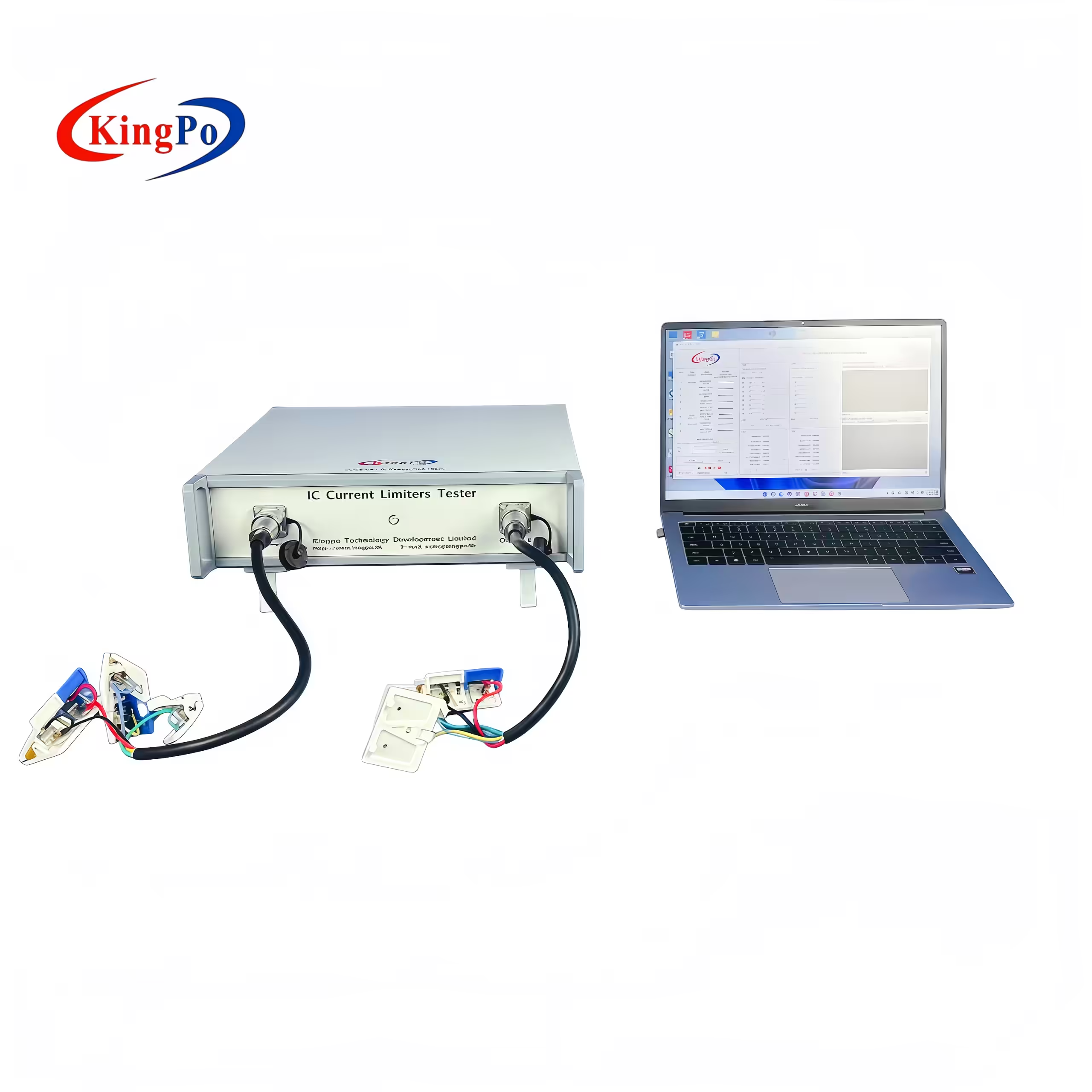
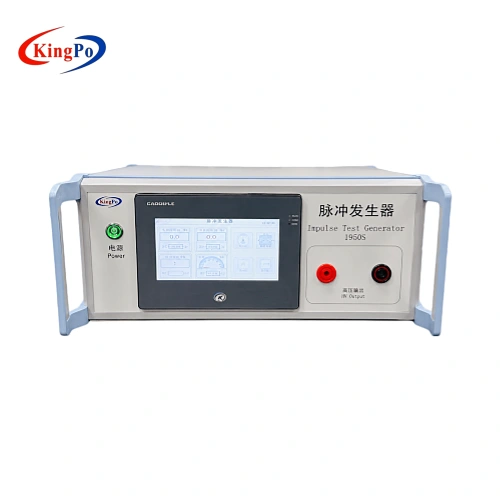
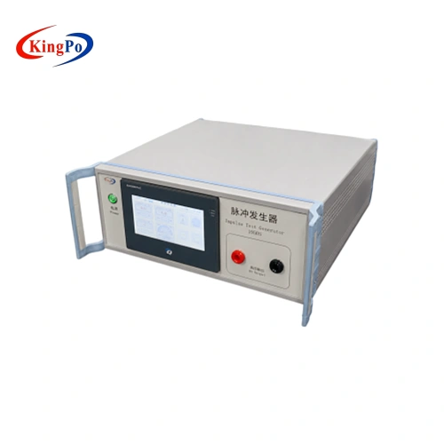
Table D.1 impulse test generator top angle product photo
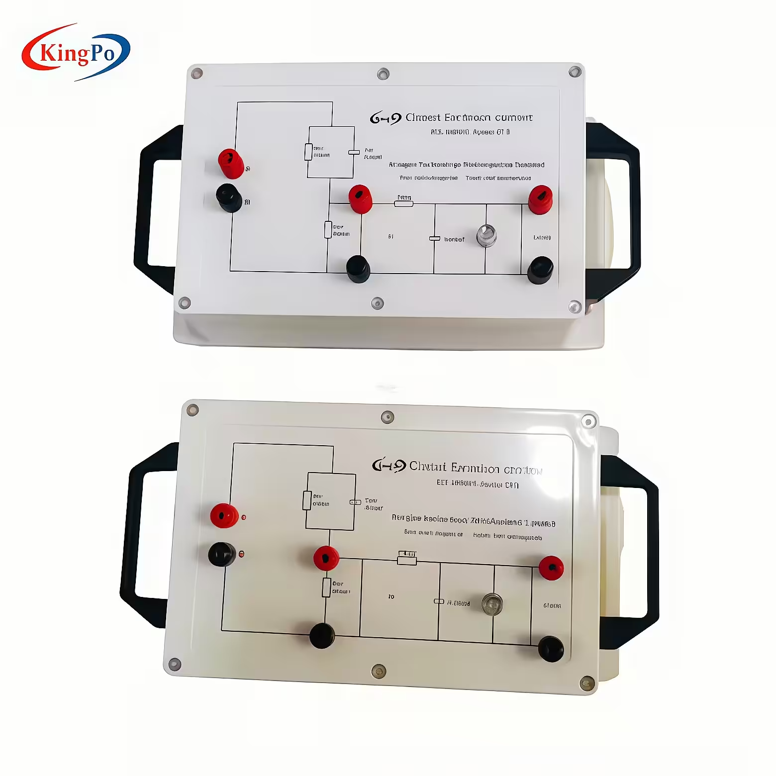
IEC 62368-1 Table D.1 impulse test generator KP-1950S front view
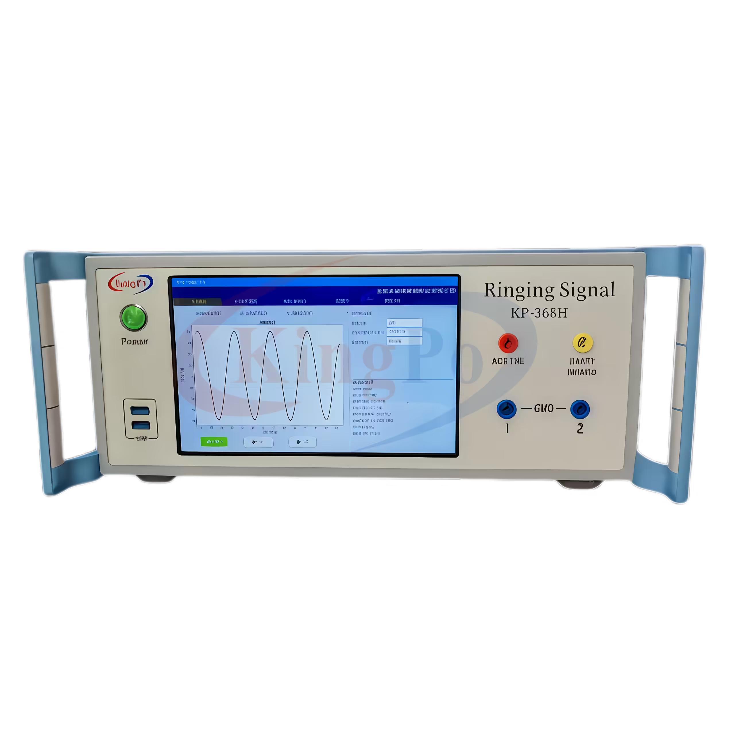
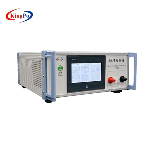
KP-1950S impulse test generator left front angle view in laboratory
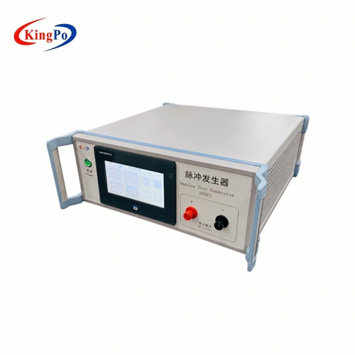
IEC 62368-1 impulse test generator right side ventilation view
Table D.1 impulse test generator top angle product photo
IEC 62368-1 Table D.1 impulse test generator KP-1950S front view
KP-1950S impulse test generator left front angle view in laboratory
IEC 62368-1 impulse test generator right side ventilation view

IEC 62368-1 Table D.1 Impulse Test Generator

The KP-1950S is an IEC 62368-1 Table D.1 Impulse Test Generator designed for AV/ICT equipment safety testing. It provides controlled high-voltage impulse outputs for Table D.1 related test circuits, including 10/700 μs and 1.2/50 μs pulse waveforms.

This impulse test generator is suitable for safety laboratories, certification preparation, R&D verification and manufacturer quality control where repeatable impulse voltage testing is required for information technology equipment, communication equipment, power supplies and related electronic products.

  • Applicable Standard: IEC 62368-1 Table D.1
  • Test Type: Impulse voltage test generator
  • Test Circuits: Table D.1 Circuit 1 and Circuit 2
  • Pulse Waveforms: 10/700 μs and 1.2/50 μs
  • Output Voltage: 0–4 kV for 10/700 μs, 0–6 kV for 1.2/50 μs
  • Control System: PLC programmable controller
  • Operation Interface: 7-inch color touchscreen
  • Typical DUT: AV equipment, IT equipment, communication equipment, network equipment, adapters and power supplies

Product Overview

The KP-1950S Impulse Test Generator is designed for IEC 62368-1 Table D.1 related impulse voltage testing. It generates specified impulse waveforms used to evaluate whether AV/ICT equipment and related circuits can withstand transient electrical stress under standard-defined test conditions.

For laboratories and manufacturers, the main concern is not only the maximum output voltage. The more important point is whether the generator provides the correct pulse waveform, voltage range, polarity switching and test sequence required by the applicable test circuit. The KP-1950S supports both 10/700 μs and 1.2/50 μs impulse waveforms, making it suitable for projects that require Table D.1 related circuit verification.

This model should not be treated as a general signal generator. It is a dedicated impulse voltage test instrument for safety-related impulse testing of AV/ICT equipment, communication equipment and associated electronic products.
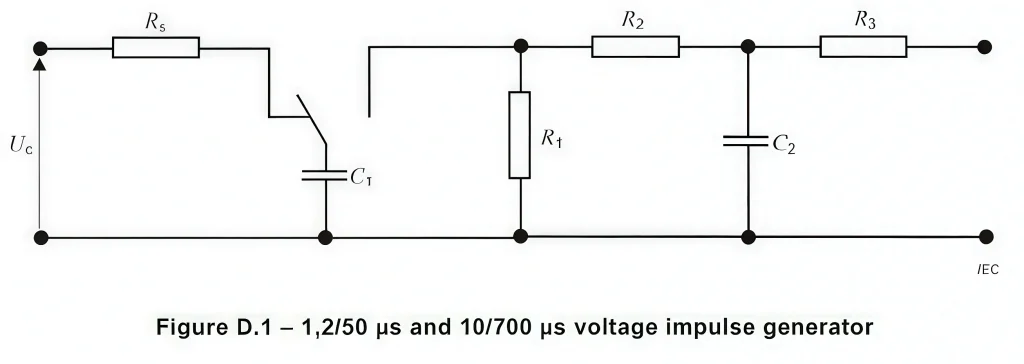
IEC 62368-1 Figure D.1 voltage impulse generator circuit for 1.2/50 μs and 10/700 μs testing

Technical Specifications

The main specifications of the IEC 62368-1 Table D.1 Impulse Test Generator are organized below for quick laboratory and purchasing review.

Impulse Output and Waveform

Item Specification
Product Model KP-1950S
Applicable Standard IEC 62368-1 Table D.1 / GB4943.1 related testing
Test Type Impulse voltage test generator
Test Circuit Table D.1 Circuit 1 / Circuit 2
Pulse Waveform 1 10/700 μs
Output Voltage for 10/700 μs 0–4 kV, continuously adjustable
Waveform Error for 10/700 μs ±20%
Pulse Waveform 2 1.2/50 μs
Output Voltage for 1.2/50 μs 0–6 kV, continuously adjustable
Waveform Error for 1.2/50 μs ±20%
Voltage Display Accuracy ±5% ±3 digits

Control and Test Settings

Item Specification
Charge / Discharge Time Setting 1–999 s
Time Setting Accuracy ±1%
Test Cycles 0–999 times
Test Count Accuracy ±1 count
Output Voltage Polarity Positive and negative alternating switching
Monitoring Output Voltage Ratio 1:1000
Control System PLC programmable controller
Display / Operation 7-inch color touchscreen
Operation Menu Chinese / English interface

Protection, Power and Structure

Item Specification
Protection Function Overcurrent and overvoltage protection
High Voltage Transformer Power 400 VA
Input Power AC 220 V ±10%, 50 Hz ±2 Hz
Dimensions Approx. 640 × 460 × 320 mm

Waveform and Test Circuit Selection

IEC 62368-1 Table D.1 related impulse testing may involve different impulse circuits and waveform requirements. Before selecting the equipment configuration, laboratories should confirm which test circuit is required by the product test plan.

10/700 μs Impulse WaveformThe 10/700 μs impulse waveform is typically associated with impulse testing that simulates lightning interference in communication networks. It is useful for AV/ICT products and communication-related equipment where transient stress from external network conditions needs to be considered.
1.2/50 μs Impulse WaveformThe 1.2/50 μs impulse waveform is commonly used to simulate transient voltage conditions in distribution systems. This test condition helps evaluate whether equipment insulation and protective circuits can withstand short-duration high-voltage impulses.
Circuit 1 and Circuit 2 ConfirmationCircuit 1 and Circuit 2 may use different component configurations and pulse characteristics. The required circuit should be checked against the applicable standard version, DUT category and laboratory procedure before testing.

Circuit Configuration Reference

The Table D.1 test network includes defined circuit parameters for different impulse waveforms. A typical configuration may include capacitors and resistors selected according to the required circuit type.

Circuit Type Test Pulse C1 C2 R1 R2 R3
Circuit 1 10/700 μs 20 μF 0.2 μF 50 Ω 15 Ω 25 Ω
Circuit 2 1.2/50 μs 1 μF 30 nF 76 Ω 13 Ω 25 Ω

Note: The actual test arrangement should follow the applicable IEC 62368-1 / GB4943.1 standard version and laboratory procedure. The impulse waveform may vary under different load conditions.

Design and Operation Features

PLC Programmable ControlManages test parameters, working status and test sequence to support repeatable testing and reduce manual operation errors. 7-Inch Color TouchscreenSupports parameter setting and operation monitoring with Chinese and English menu operation.
Dual Waveform CapabilitySupports both 10/700 μs and 1.2/50 μs impulse waveforms for Table D.1 related test plans. Adjustable Output VoltageProvides 0–4 kV for 10/700 μs and 0–6 kV for 1.2/50 μs impulse testing.
Programmable Test CyclesCharge/discharge time and test count can be programmed for repeated impulse application and batch verification. Alternating Polarity OutputSupports positive and negative alternating polarity switching when both impulse polarities are required.
Protection FunctionsOvercurrent and overvoltage protection functions help improve operational safety and protect the instrument during high-voltage impulse testing.

Typical Applications

The KP-1950S is used for IEC 62368-1 Table D.1 related impulse voltage testing of AV/ICT and electronic products.

  • Audio/video equipment safety testing
  • Information technology equipment testing
  • Communication equipment verification
  • Network equipment and interface safety testing
  • Power supply and adapter impulse withstand testing
  • R&D design margin evaluation
  • Pre-compliance testing before certification
  • Factory quality control and batch sampling
  • Electrical safety laboratories and product certification preparation

What the Test Helps Evaluate

Impulse voltage testing helps engineers evaluate whether the equipment design can maintain safety performance when exposed to defined transient electrical stress.

The test may help identify weak insulation paths, insufficient clearance or creepage margin, protective circuit weakness, component withstand limitations, unexpected breakdown, flashover, abnormal response under transient voltage conditions, or design risks before formal certification testing.

Note: This section is not a replacement for the standard test procedure. The final connection method, waveform selection, voltage setting and pass/fail judgment should follow the applicable IEC 62368-1 / GB4943.1 requirement and the laboratory’s internal safety procedure.

Buyer’s Selection Notes

Before purchasing an IEC 62368-1 impulse test generator, buyers should confirm the following items:
Applicable standard versionConfirm whether the project follows IEC 62368-1, GB4943.1 or another national adoption.
Required test circuitConfirm whether the test requires Table D.1 Circuit 1, Circuit 2, or both circuit configurations.
Required waveformConfirm whether the test plan requires 10/700 μs, 1.2/50 μs, or both impulse waveforms.
Required output voltageConfirm the required voltage level and calibration points. This model supports 0–4 kV for 10/700 μs and 0–6 kV for 1.2/50 μs.
DUT type and connection arrangementThe product type, interface type and test connection method may affect the required test setup.
Documentation requirementFor laboratory and certification preparation, buyers may need datasheets, calibration documents, factory inspection records or configuration confirmation.

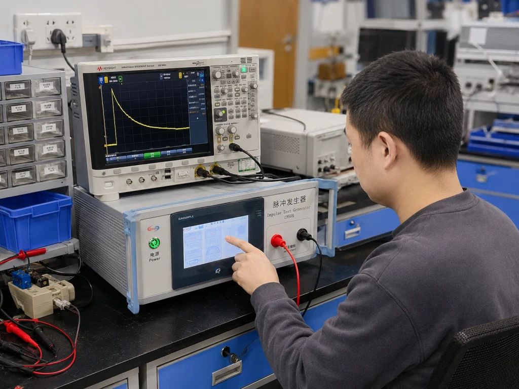
KP-1950S impulse test generator laboratory testing scene with oscilloscope

Typical Operation Workflow

  1. Confirm the applicable standard clause, waveform and Table D.1 circuit type.
  2. Prepare the DUT according to the laboratory test procedure.
  3. Select the required impulse waveform: 10/700 μs or 1.2/50 μs.
  4. Set the output voltage, charge/discharge time and number of test cycles.
  5. Confirm polarity setting and test connection arrangement.
  6. Check grounding, insulation clearance and operator safety conditions before testing.
  7. Start the programmed test sequence and monitor the DUT response.
  8. Record the test result, abnormal behavior or visible breakdown condition.
  9. After testing, discharge the circuit safely before handling the DUT.

Safety Note: High-voltage impulse testing should only be performed by trained personnel under controlled laboratory conditions. The operator should follow the applicable standard, equipment manual and internal safety procedure.

Typical Observations During Testing

During impulse voltage testing, engineers usually observe whether the DUT shows insulation breakdown, flashover, abnormal discharge, protective component failure, malfunction, permanent damage or other unexpected behavior.

For pre-compliance work, the result can help engineers identify design areas that may require review before formal certification. Final pass/fail judgment should always follow the applicable standard requirement and the laboratory’s approved test procedure.

Impulse Test Generator for IEC 62368-1 Table D.1

The term “impulse test generator” can refer to different waveforms, circuits and test purposes. The KP-1950S is specifically intended for IEC 62368-1 Table D.1 related impulse voltage testing.

It should not be confused with a general laboratory signal generator, arbitrary waveform generator or unrelated EMC surge simulator. For correct selection, the required waveform, voltage range, circuit type and DUT connection method should be confirmed before ordering.

Compliance & Regulatory Assurance

  • The KP-1950S supports IEC 62368-1 Table D.1 and GB4943.1 related impulse voltage testing for AV, IT and communication equipment. It helps laboratories and manufacturers perform standard-based verification during R&D, pre-compliance checks and routine quality control.
  • To support compliance work, the required standard version, test circuit, waveform, voltage level, DUT connection method and documentation needs should be confirmed before ordering. Calibration-related documents and technical datasheets can be provided according to project requirements.
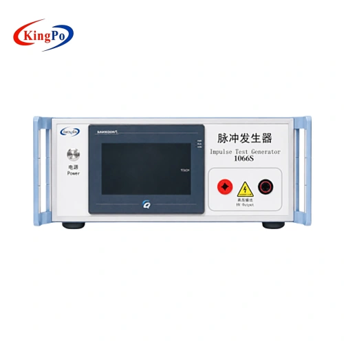
IEC 62368-1 Table D.1 Impulse Test Generator Datasheet
KP-1950S datasheet with 10/700 μs and 1.2/50 μs waveform information, technical specifications and Figure D.1 circuit reference.

Technical Inquiry & Expert Support

For correct model selection, please share the following information when sending an inquiry. This helps confirm whether the KP-1950S matches your IEC 62368-1 Table D.1 test plan before quotation or purchase.

Information Needed Example
Applicable standard IEC 62368-1 / GB4943.1
Required circuit Table D.1 Circuit 1, Circuit 2, or both
Required waveform 10/700 μs, 1.2/50 μs, or both
Required voltage range 0–4 kV / 0–6 kV or specific test point
DUT type AV equipment, IT equipment, communication equipment, adapter, power supply
Documentation needs Datasheet, calibration document, inspection record

KingPo can help confirm whether the KP-1950S matches your test plan before quotation or purchase. This helps reduce configuration errors and ensures the equipment is suitable for your laboratory, certification preparation or production quality control use.

Impulse test generator Video

IEC 62368-1 Table D.1 Impulse Test Generator

FAQ

What is the KP-1950S Impulse Test Generator mainly used for?
The KP-1950S is used for IEC 62368-1 Table D.1 related impulse voltage testing of AV/ICT equipment, communication equipment, adapters, power supplies and similar electronic products. It helps laboratories and manufacturers apply specified impulse waveforms to evaluate insulation withstand ability, protective circuit behavior and possible breakdown risks under transient voltage conditions.
Does this generator support both Table D.1 Circuit 1 and Circuit 2?
Yes, the KP-1950S is designed to support Table D.1 related impulse test requirements, including Circuit 1 and Circuit 2 configurations. Before ordering, the required circuit should be confirmed according to the applicable standard version, DUT type and laboratory test plan, because different circuits correspond to different waveform and component configurations.
What is the difference between the 10/700 μs and 1.2/50 μs impulse waveforms?
The 10/700 μs waveform is typically associated with communication network transient conditions, while the 1.2/50 μs waveform is commonly used for transient voltage conditions related to power distribution systems. The correct waveform should be selected based on the test circuit required by IEC 62368-1 Table D.1 and the product’s actual interface or supply condition.
What output voltage ranges are available?
For the 10/700 μs waveform, the output voltage range is 0–4 kV. For the 1.2/50 μs waveform, the output voltage range is 0–6 kV. The voltage can be adjusted according to the required test level, but the final setting should follow the applicable standard, test plan and laboratory procedure.
Is the KP-1950S the same as a general EMC surge generator?
No. Although both instruments may generate high-voltage impulses, the KP-1950S is intended for IEC 62368-1 Table D.1 related impulse voltage testing. A general EMC surge generator may follow different standards, waveforms, coupling networks and test methods. Buyers should confirm the exact standard clause and waveform before selecting equipment.
How should users confirm whether Circuit 1 or Circuit 2 is needed?
The required circuit should be confirmed from the product’s applicable standard clause, test category, interface type and certification test plan. For example, communication-related interfaces and power-related transient tests may require different waveform conditions. When unsure, it is better to share the DUT type and test requirement for configuration confirmation before quotation.
Can the test sequence be programmed?
Yes. The KP-1950S supports programmable charge/discharge time and test cycles. The charge and discharge time can be set from 1 to 999 seconds, and the number of tests can be set from 0 to 999 times. This is useful for repeated impulse application, pre-compliance verification and routine laboratory testing.
Does the equipment support positive and negative polarity testing?
Yes. The generator supports positive and negative alternating polarity switching. This is important because some test plans may require impulses to be applied in both polarities to evaluate whether the DUT has different withstand behavior under positive and negative transient stress.
What should be prepared before performing the test?
Before testing, the operator should confirm the required waveform, voltage level, circuit type, DUT connection method, grounding condition and safety clearance. High-voltage impulse testing should be performed only by trained personnel. The DUT and test leads should be connected according to the applicable standard and laboratory safety procedure.
Can KingPo provide calibration or technical documents for this equipment?
Technical datasheets and calibration-related documents can be provided according to project requirements. For certification laboratories or regulated internal testing, customers should confirm the required calibration points, document format and applicable standard version before ordering, so the supplied documentation can better match the laboratory’s quality system requirements.

Related Products

Related News

Three Vertical Bar Signal Generator streamlines IEC 62368-1 compliance by ensuring accurate display testing and reliable safety certification.

Abstract & Technical Summary IEC 62368-1 foreign object detection (FOD) testing assesses wireless power transmitter safeguards against excessive metal object […]

Compare KINGPO KP-1060 with top ESD generator and capacitor discharge testers to find the best option for safe, accurate capacitor discharge testing.
IEC 62368-1 Clause 9.6.2 Wireless Charging Foreign Object Temperature Rise Test Kit streamlines compliance, ensuring safe and certified wireless charging devices.
KP-1065S Pulse Voltage Generator boosts surge testing efficiency, safety, and IEC 62368-1 compliance for advanced electronics and production lines.
Impulse test generator features for IEC 62368-1: dual waveforms, adjustable voltage, and safety controls make compliance and electrical testing simple.

Essential equipment for residual voltage testing under IEC 60601-1, IEC 60335-1, IEC 61010-1, IEC 62368-1 and similar safety standards. 1. […]

Key Takeaways IEC 60695 series standardizes fire hazard testing for electrotechnical products using glow-wire (GWEPT/GWFI/GWIT), needle flame, and 50W/500W horizontal/vertical […]

Scroll to Top

Get A Free Quote Now !

Contact Form
If you have any questions, please do not hesitate to contact us.