Abstract
Unexpected behavior during IEC 61000-4-5 surge immunity testing is frequently attributed to the surge generator before the complete test configuration has been examined. In practice, an absence of apparent surge output, interruption of EUT power, abnormal voltage or current readings, or poor repeatability may originate from several elements of the test system, including the coupling/decoupling network, EUT supply path, selected coupling mode, source impedance, measurement point, or operating state of the EUT.
This technical note discusses these failure modes from a laboratory diagnostic perspective. The objective is not to provide a repair procedure for a particular instrument, but to establish a structured basis for distinguishing configuration-related effects from conditions that warrant formal generator verification or qualified technical service.
Contents
Background and Scope
IEC 61000-4-5 establishes test methods for evaluating the immunity of electrical and electronic equipment to specified surge disturbances. The test is intended to reproduce defined transient conditions associated with switching events and indirect effects of lightning within the scope of the standard. It should not be interpreted as an insulation withstand test or as a simulation of a direct lightning strike.
The standard forms part of the wider body of IEC standards used to define electromagnetic compatibility test methods, while the applicable product standard determines the relevant ports, test levels, coupling arrangements, operating conditions and performance criteria for the EUT.
This distinction is important in troubleshooting. A surge generator can operate normally while the overall test remains invalid because the wrong port, coupling network, source impedance or EUT operating state has been selected. Conversely, an abnormal EUT response does not in itself demonstrate that the generator output is incorrect.
For this reason, diagnostic work should begin with the complete test arrangement rather than with an isolated assessment of the pulse generator.
Diagnostic Framework
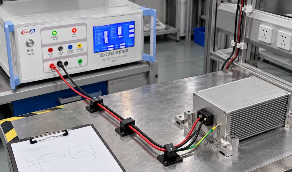
A reproducible diagnosis requires the actual test configuration to be documented before any setting is changed. At minimum, the record should identify the applicable product standard and edition, EUT supply conditions, EUT operating mode, port under test, coupling arrangement, surge level, polarity, phase angle where applicable, pulse interval and the method used to monitor EUT performance.
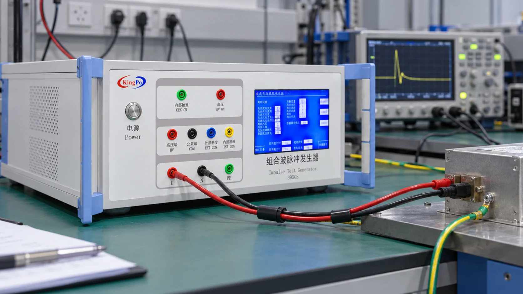
The physical wiring should then be compared with the documented test plan. This comparison is particularly important where several coupling paths or external networks are available, since a generator indication only confirms the state of the generator; it does not independently establish that the specified disturbance has been applied to the intended EUT port.
| Observed Condition | Primary Diagnostic Consideration | Basis for Escalation |
|---|---|---|
| No apparent surge output | Operating state, interlock, alarm condition, program status and selected output path | Persistent alarm, failed safety condition or unsuccessful formal verification |
| Loss of EUT power | EUT supply route, CDN rating, protective trip and EUT reset behavior | Repeated shutdown or operation outside published supply limits |
| Unexpected voltage or current | Measurement condition, source impedance, load condition and measurement point | Failure to meet the prescribed generator verification method |
| Poor repeatability | EUT state, polarity, phase, coupling path, cable arrangement and recovery between pulses | Conditions cannot be reproduced under controlled test settings |
Changing several parameters simultaneously should be avoided during diagnosis. A single-variable approach preserves traceability and makes it possible to identify which condition altered the observed result.
Safety consideration. Troubleshooting must not involve bypassing an interlock, protective trip or discharge procedure. If unsafe EUT behavior is observed, the test should be stopped and the equipment returned to a safe state before connections are changed.
Common Failure Modes
Absence of Apparent Surge Output
Where no surge is observed, the initial assessment should be based on the operating state reported by the instrument. Safety interlocks, output enable conditions, selected test program and the intended coupling path should be confirmed before the generator is triggered again.
A generator may intentionally inhibit pulse generation if a required safety condition has not been satisfied. In such cases, the displayed alarm or status message is diagnostically more useful than repeatedly attempting to initiate the pulse. A persistent alarm should be evaluated using the manufacturer’s specified diagnostic procedure.
The response of the EUT should not be used as the sole indication of pulse generation. An unchanged display or normal EUT operation does not demonstrate that no disturbance was applied. Where generator output itself is in question, the appropriate verification method is required.
Loss of EUT Power During the Test
Loss of EUT power during a surge should not immediately be attributed to the generator. The generator mains supply and the supply delivered to the EUT are separate parts of the test arrangement and should therefore be evaluated independently.
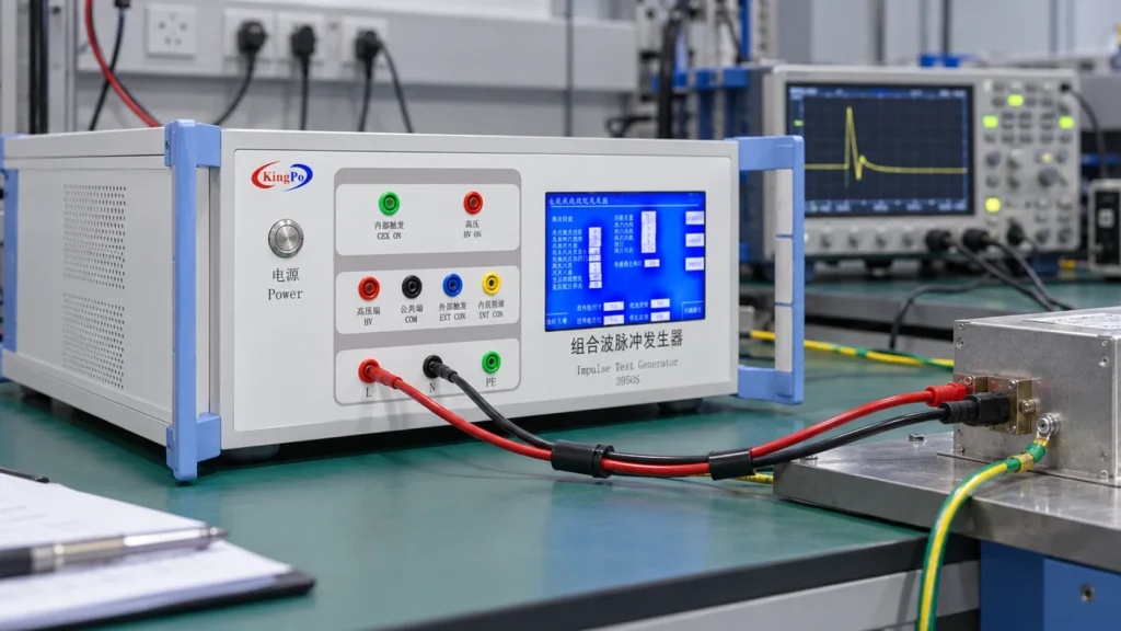
The EUT supply path commonly includes a coupling/decoupling network. Its voltage and current ratings form part of the test-system limits, and operation of its protection may produce an apparent EUT power interruption even though surge generation remains normal. The EUT itself may also reset or enter a protective state in response to the applied disturbance.
For diagnosis, it is therefore necessary to distinguish among an EUT reset, interruption of the external EUT supply, and operation of CDN protection. The status of the generator, CDN and EUT should be recorded before the test system is reset.
Incorrect Test Port or Coupling Path
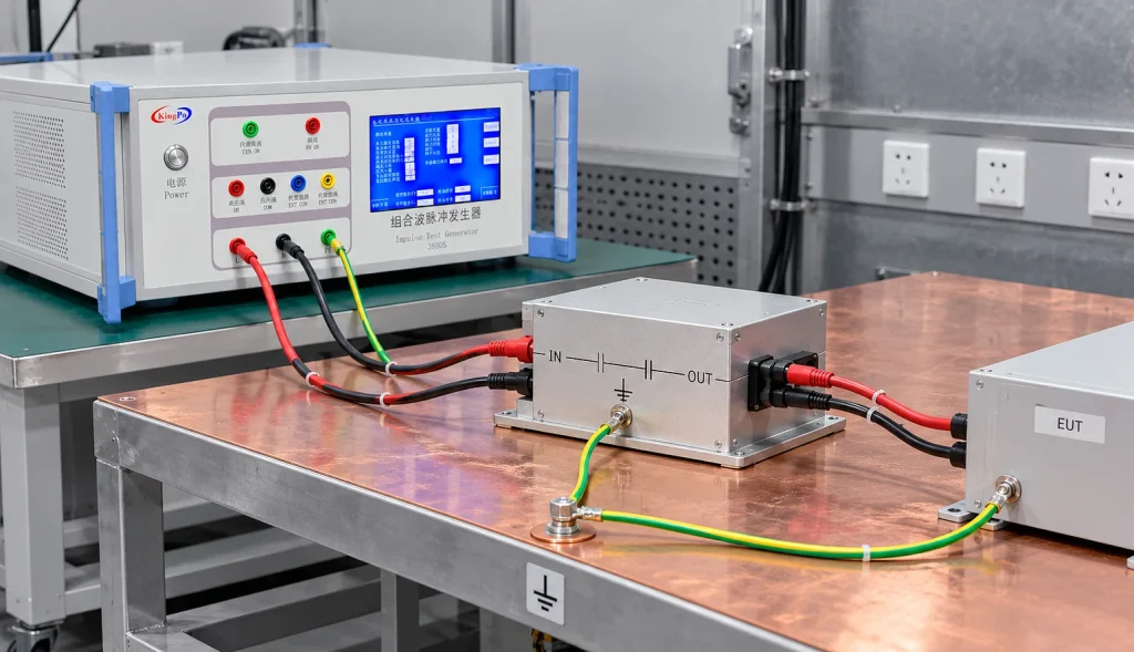
A valid pulse indication at the generator does not independently demonstrate that the required EUT port has received the specified test. The physical connection, selected coupling path and required source-impedance arrangement must correspond to the test plan.
Line-to-line and line-to-ground tests require different conductor combinations. In addition, power ports and signal or communication ports may require different coupling networks or generator characteristics. The suitability of a coupling arrangement should therefore be established from the applicable requirement rather than inferred from the generator voltage setting.
Increasing the surge level cannot compensate for an incorrect coupling path. If the intended path cannot be established or verified, the configuration should be reviewed before further testing is performed.
Unexpected Voltage or Current Readings
For the combination-wave surge generator commonly associated with power-port testing, the 1.2/50 μs voltage waveform and 8/20 μs current waveform are defined under different reference conditions. The former refers to open-circuit voltage, whereas the latter refers to short-circuit current.
These quantities should not be interpreted as two independent waveforms expected to remain unchanged after connection to the EUT. Once the test system is loaded, the observed voltage and current are influenced by the generator source impedance, coupling network, EUT impedance, measurement point and characteristics of the measurement system.
A waveform recorded at an arbitrary point on the EUT is therefore not equivalent to formal generator verification. Where output performance is in question, the comparison should be made under the verification conditions specified for the generator and with suitable calibrated measuring equipment.
Variation Between Nominally Identical Tests
A change in EUT response between nominally identical surges does not necessarily indicate poor generator repeatability. The operating state of the EUT, applied load, polarity, phase angle, coupling path, pulse interval, cable arrangement and recovery state may all affect the observed response.
The EUT should be returned to the specified operating condition between pulses whenever required by the applicable procedure. Monitoring criteria should also be defined before the test. A transient display disturbance, communication interruption, automatic reset, protective shutdown and permanent loss of function represent different EUT responses and should not be treated as equivalent observations.
Acceptance of these responses is determined by the relevant product standard and specified performance criteria, not by the generator indication alone.
Waveform and Source-Impedance Considerations
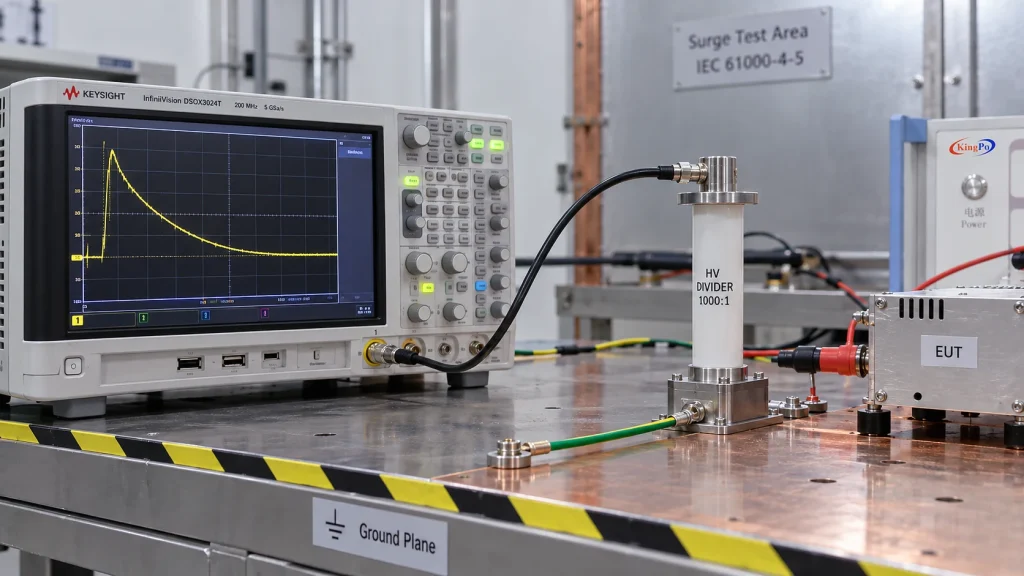
Maximum surge voltage alone does not define the electrical stress applied during a surge immunity test. Source impedance determines the relationship between the generator’s open-circuit voltage and the current available under low-impedance conditions. This parameter is therefore fundamental to interpretation of the test.
Two configurations operated at the same nominal surge voltage may not impose the same electrical conditions if their source impedances, coupling networks or EUT impedances differ. A measured current value should consequently be interpreted in relation to the applicable source impedance and load condition rather than compared directly with the open-circuit voltage specification.
Reference conditions for the combination wave
1.2/50 μs: open-circuit voltage reference waveform
8/20 μs: short-circuit current reference waveform
During troubleshooting, the measurement location, measuring device, load condition, coupling configuration, selected source impedance, surge level and polarity should therefore be documented before a trace is compared with a specification.
Repeatability of the Test Configuration
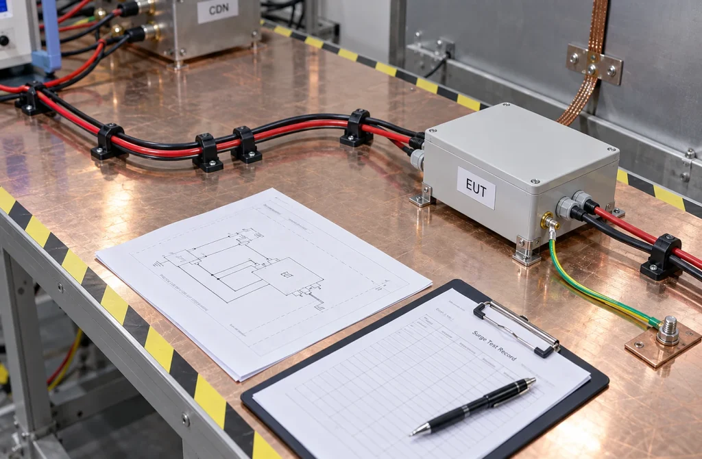
Repeatability depends on more than the programmed generator settings. Physical features of the test arrangement may influence both the applied disturbance and the observed EUT response. Cable length, routing, grounding or reference connections, auxiliary equipment and the position of the EUT should therefore remain controlled where the test procedure requires a defined arrangement.
The EUT operating condition is equally important. A unit operating under a different load, communication state or functional mode is not necessarily being tested under equivalent conditions even if the surge settings are unchanged.
A setup photograph or connection diagram recorded before testing provides a simple means of preserving the physical configuration. Where inconsistent behavior is being investigated, comparison of these records can be as important as comparison of the generator settings.
Information Required for Technical Diagnosis
Where a test result cannot be explained from the initial configuration review, the diagnostic record should contain sufficient information for another engineer to reconstruct the test. A statement such as “the surge generator is not working” does not distinguish among a configuration error, EUT response, supply interruption, measurement issue or instrument fault.
- Applicable product standard, edition and specific surge requirement
- Generator and coupling/decoupling network configuration
- EUT supply type, voltage and current
- Normal EUT operating state and applied load
- Port under test and physical connection
- Coupling path and required source impedance
- Surge level, polarity and phase angle where applicable
- Pulse interval and sequence
- Observed EUT, supply and generator behavior
- Displayed alarm, trip or protection indication
- Setup photograph or connection diagram
- Verification or calibration status where waveform performance is questioned
This level of documentation permits the diagnostic process to separate five distinct areas: the test requirement, the coupling and supply path, the EUT response, the measurement method and the condition of the test equipment.
Discussion
Surge immunity testing is a system-level activity. The generator is only one element of a configuration that also includes the coupling network, EUT supply, physical wiring, operating state, monitoring arrangement and measurement system. Troubleshooting that concentrates exclusively on generator settings can therefore overlook conditions elsewhere in the test chain.
Several apparently similar symptoms may have different origins. Loss of EUT power, for example, may result from an EUT reset, operation of an external protection device or interruption within the coupling network. Similarly, a waveform that differs from the generator’s reference waveform may simply have been measured under a loaded condition or at a location that is not intended for generator verification.
The practical consequence is that troubleshooting should preserve the original test state for as long as possible. Alarm information, protection status, measurement conditions and the response of the EUT should be recorded before the system is reset or the wiring is changed. This allows later observations to be related to the actual event rather than reconstructed from memory.
Where the documented configuration is correct but the result remains unexplained, formal verification of the generator and associated network provides a more reliable next step than repeated trial-and-error changes to the test settings.
Conclusion
Unexpected behavior during IEC 61000-4-5 testing should not automatically be classified as an instrument fault. A defensible diagnosis requires the test requirement, coupling path, EUT state and measurement condition to be considered together.
The most effective troubleshooting process is therefore based on reproducibility rather than repeated adjustment: document the initial condition, confirm the intended test path, compare measurements under equivalent conditions, and change one parameter at a time.
If the complete test arrangement has been confirmed and the observed result remains inconsistent with the prescribed verification conditions, formal equipment verification or qualified technical diagnosis is appropriate.
References
[1] IEC 61000-4-5:2014+AMD1:2017, Electromagnetic compatibility (EMC) – Part 4-5: Testing and measurement techniques – Surge immunity test.
[2] AMETEK CTS, technical guidance relating to IEC 61000-4-5 surge testing and coupling/decoupling networks.