Cable fire safety is an important compliance consideration for building wiring, fire alarm circuits, emergency power systems, transportation infrastructure, industrial facilities and other installations where cable behaviour during fire can directly affect system safety.
The Middle East provides a useful example of how cable fire testing is developing from a single-equipment requirement into a broader laboratory capability. UL Solutions established its cable fire safety and performance laboratory in Abu Dhabi to provide regional manufacturers, cable suppliers and project stakeholders with access to electrical and optical cable fire testing without necessarily sending specimens to laboratories in Europe, Asia or other regions.
UL publicly describes testing capabilities including single-cable flame propagation, bunched-cable flame spread, smoke and acid-gas assessment, as well as circuit-integrity tests involving fire, water and mechanical shock. Regional Civil Defense requirements, infrastructure specifications, construction projects and export compliance have all contributed to demand for local cable fire testing capability.
For cable manufacturers and laboratory engineers, however, the most important point is not where the laboratory is located. It is that the term “cable fire testing” does not describe one test, one standard or one machine.
Engineering distinction:
-
IEC 60332 primarily evaluates reaction to fire and flame propagation.
-
IEC 60331 addresses a fundamentally different performance objective:
-
whether a cable can maintain circuit integrity while exposed to specified fire conditions,
-
sometimes together with mechanical shock or water-related test conditions.
Quick Engineering Navigation
IEC 60332 and IEC 60331 Address Different Fire-Safety Questions
The first engineering decision in a cable fire laboratory project should be based on the required performance question rather than simply on a standard number listed in a purchase request.
| Engineering Question | Typical Standard | Primary Evaluation | Typical Equipment |
|---|---|---|---|
| How far does flame propagate on one cable? | IEC 60332-1 | Single cable vertical flame propagation | Single Cable Vertical Flame Tester |
| How does fire spread through multiple cables? | IEC 60332-3 | Bunched-cable vertical flame spread | Cable Bundle Flame Propagation System |
| How much smoke is generated? | IEC 61034 | Smoke density | Cable Smoke Density Chamber |
| What combustion gases are evolved? | IEC 60754 | Halogen acid gas, acidity and conductivity | Combustion Gas Analysis System |
| Does the electrical circuit continue operating during fire? | IEC 60331 | Circuit integrity | Fire Resistance / Circuit Integrity System |
| Can the cable continue operating during fire and mechanical disturbance? | Applicable IEC 60331 part | Fire + mechanical shock | Integrated Fire and Shock System |
IEC 60332-1 Single Cable Vertical Flame Propagation
The IEC 60332-1 series addresses fire testing of a single insulated conductor, cable or optical fibre cable under defined flame exposure.
IEC 60332-1-2:2025 specifies the procedure for testing resistance to vertical flame propagation using a 1 kW pre-mixed flame. The associated apparatus is defined by IEC 60332-1-1.
One important limitation should be understood by both purchasing personnel and laboratory engineers: successful performance in a single-cable test does not demonstrate the behaviour of cables installed together as a group. Bunched-cable installations are addressed separately by IEC 60332-3.
What Engineers Should Check in an IEC 60332-1 Tester
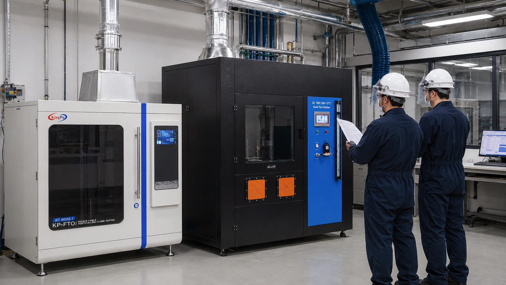
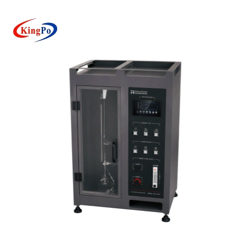
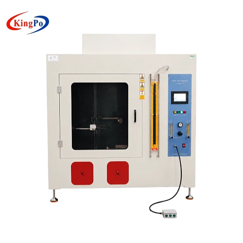
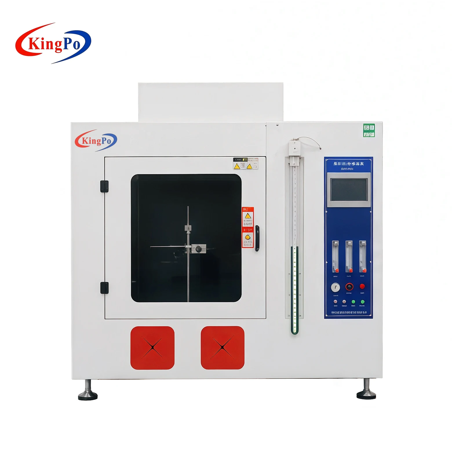
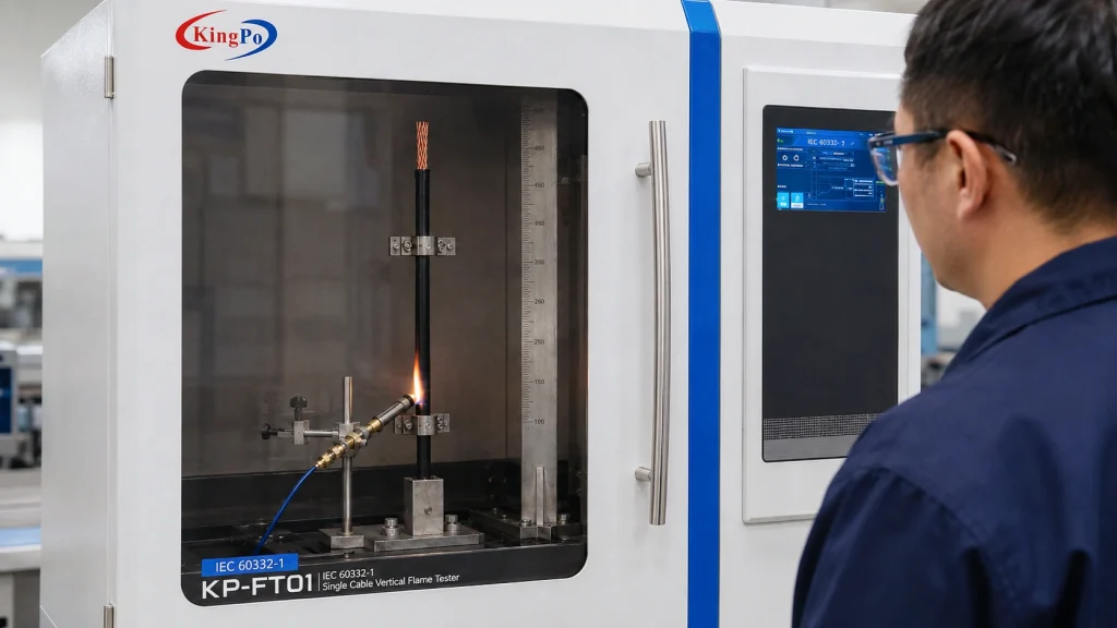
For single-cable testing, KingPo provides the IEC 60332-1 Single Cable Vertical Flame Propagation Tester, incorporating the combustion chamber, burner arrangement, specimen support and associated control functions required for this type of evaluation.
A request stating only “IEC 60332 tester” is incomplete. Engineers should first establish whether the requirement is IEC 60332-1 single-cable testing or IEC 60332-3 bunched-cable testing.
IEC 60332-3 Bunched Cable Flame Spread Testing
When several cables are installed together, their combined non-metallic material, spacing, mounting arrangement and airflow can produce substantially different fire behaviour from that observed on a single isolated cable.
IEC 60332-3-10 defines the apparatus and arrangement used for assessing vertical flame spread of vertically mounted bunched electrical or optical fibre cables.
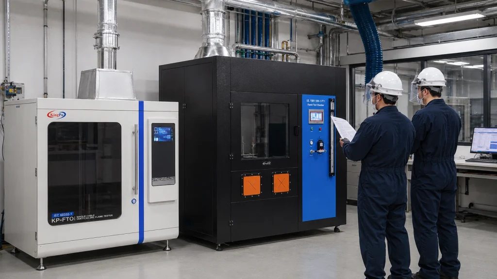
In practical laboratory terms, this is no longer a compact cabinet test. The system typically requires a large test enclosure, vertical cable ladder, defined specimen loading, burner system, controlled air supply and substantially greater exhaust capacity.
| Parameter | IEC 60332-1 | IEC 60332-3 |
|---|---|---|
| Specimen | Single cable | Multiple cables on defined ladder |
| Primary objective | Vertical flame propagation | Flame spread through cable bunch |
| Test scale | Compact laboratory equipment | Large test installation |
| Air supply | Controlled chamber condition | Defined airflow becomes part of system design |
| Exhaust requirement | Moderate | Substantially larger smoke and heat load |
| Project type | Usually individual equipment | Often a laboratory engineering project |
UL 1581 VW-1 and CSA FT1 Cable Flame Testing
Laboratories serving manufacturers exporting to North America may also require vertical wire and cable flame testing according to UL and CSA methods in addition to IEC requirements.
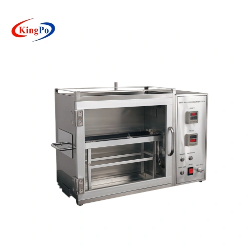
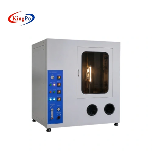
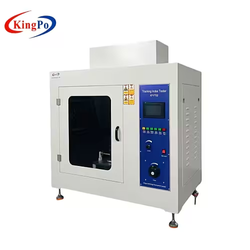
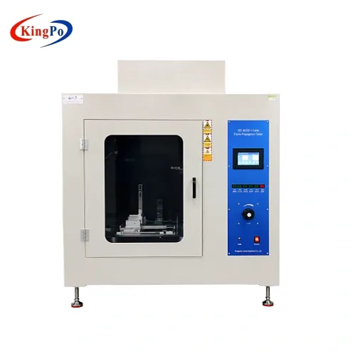
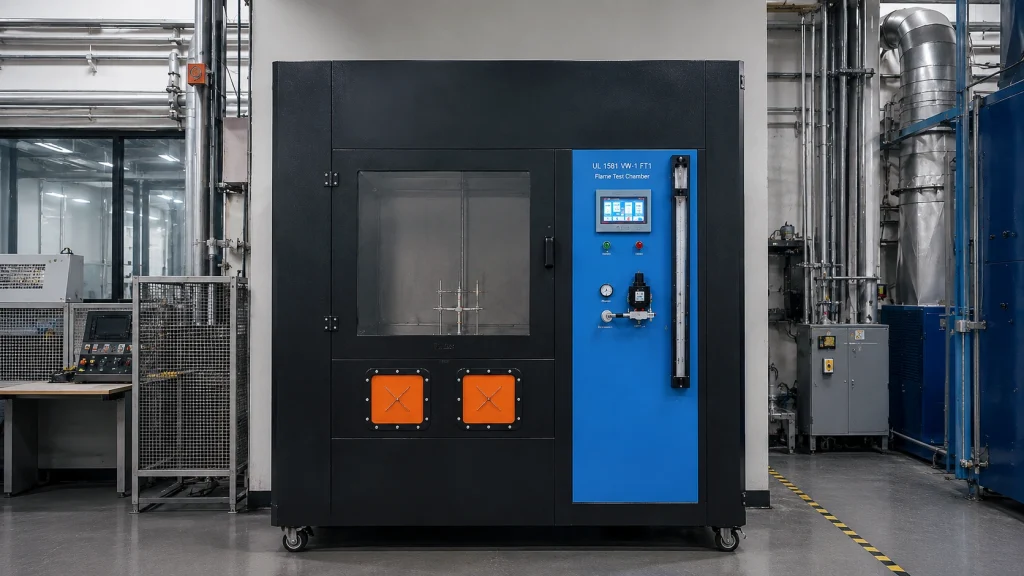
For this application, KingPo provides the UL 1581 VW-1 / CSA FT1 Flame Test Chamber, configured for repeated flame application to vertically mounted wire and cable specimens.
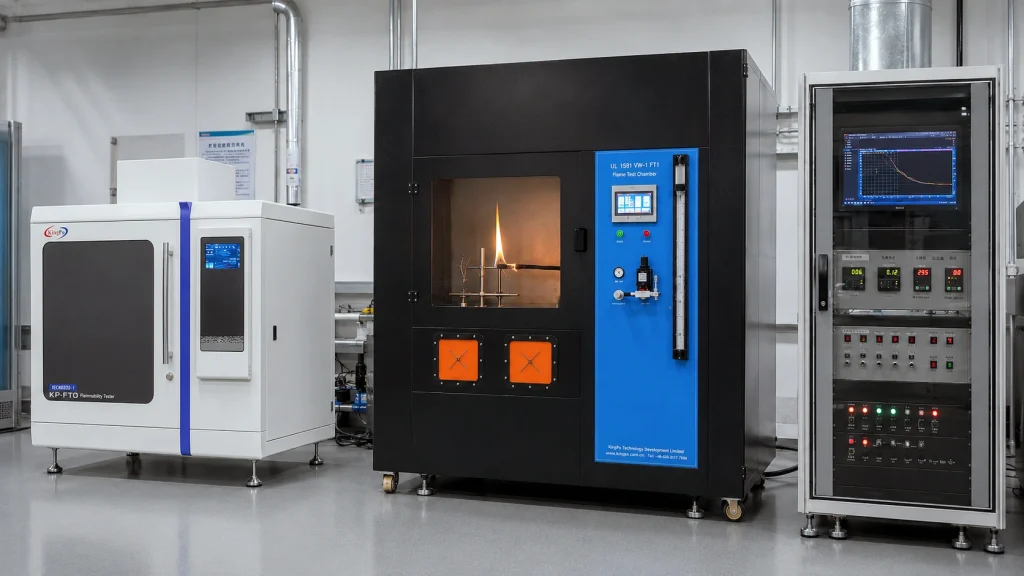
IEC 60332, UL 1581 VW-1 and CSA FT1 should not be treated as interchangeable simply because all of them involve a flame and a vertically mounted cable specimen. Burner configuration, flame application sequence, specimen arrangement, timing, observation method and acceptance criteria must follow the exact referenced standard.
Smoke Density and Combustion-Gas Testing
Flame spread is only one aspect of cable fire performance. Burning polymeric cable materials can also produce dense smoke and corrosive combustion products that affect visibility, evacuation, sensitive equipment and occupied spaces.
IEC 61034 — Smoke Density
The IEC 61034 series addresses measurement of smoke density from cables burning under defined conditions. The test normally requires a dedicated smoke-density chamber with an optical measurement path rather than an accessory installed inside an IEC 60332 flame chamber.
For a laboratory project, the equipment scope therefore extends beyond the combustion source to the chamber geometry, optical receiver and transmitter, calibration arrangement, smoke extraction and post-test cleaning requirements.
IEC 60754 — Gases Evolved During Cable Combustion
The IEC 60754 series addresses gases evolved during combustion of cable materials. IEC 60754-1 is associated with determination of halogen acid gas content, while IEC 60754-2 evaluates potential corrosivity through acidity and conductivity measurements.
This type of testing introduces a different measurement chain involving controlled combustion, gas capture, absorption solutions and analytical measurement. It should therefore be treated as a separate laboratory capability rather than an extension of a vertical flame tester.
IEC 60332 flame propagation, IEC 61034 smoke density and IEC 60754 combustion-gas testing involve different measurement principles. A cable fire laboratory may therefore require several dedicated test stations rather than one universal combustion tester.
Fire Resistance Is Not the Same as Flame Retardancy
This distinction is particularly important for fire alarm circuits, emergency lighting, evacuation systems, critical control systems and other life-safety applications where electrical operation may need to continue after a fire has already started.
IEC 60332 primarily asks how a cable reacts to flame. IEC 60331 asks a different engineering question:
This is normally described as circuit-integrity testing. The test specimen is not simply burned and inspected afterwards; its electrical function is monitored during the test.
IEC 60331 Is a Standard Family — Diameter and Voltage Matter
A common purchasing error is to request an “IEC 60331 tester” without identifying the applicable part, cable diameter, cable voltage or required fire scenario.
| Standard | Typical Scope | Important Selection Point |
|---|---|---|
| IEC 60331-1:2018 | Circuit integrity under fire with mechanical shock for specified cables up to and including 0.6/1.0 kV. | Applicable to cables with overall diameter greater than 20 mm. |
| IEC 60331-2:2018 | Circuit integrity under fire with mechanical shock for specified cables up to and including 0.6/1.0 kV. | Applicable to cables with overall diameter not exceeding 20 mm. |
| IEC 60331-3:2018 | Fire and mechanical shock testing using a metal enclosure. | A separate method; compliance with one IEC 60331 part should not automatically be interpreted as compliance with another. |
| IEC 60331-4:2024 | Circuit integrity for higher-voltage power cables above 0.6/1.0 kV up to and including 18/30 kV. | Includes fire and mechanical-shock requirements and optional water-related protocol guidance. |
The IEC 60331 methods also involve continuity checking, defined specimen arrangements, failure criteria and test reporting. Depending on the relevant part, accurate control of fuel and air supply and reliable electrical monitoring become essential parts of the test system.
Why an IEC 60331 System Is More Than a Flame Chamber
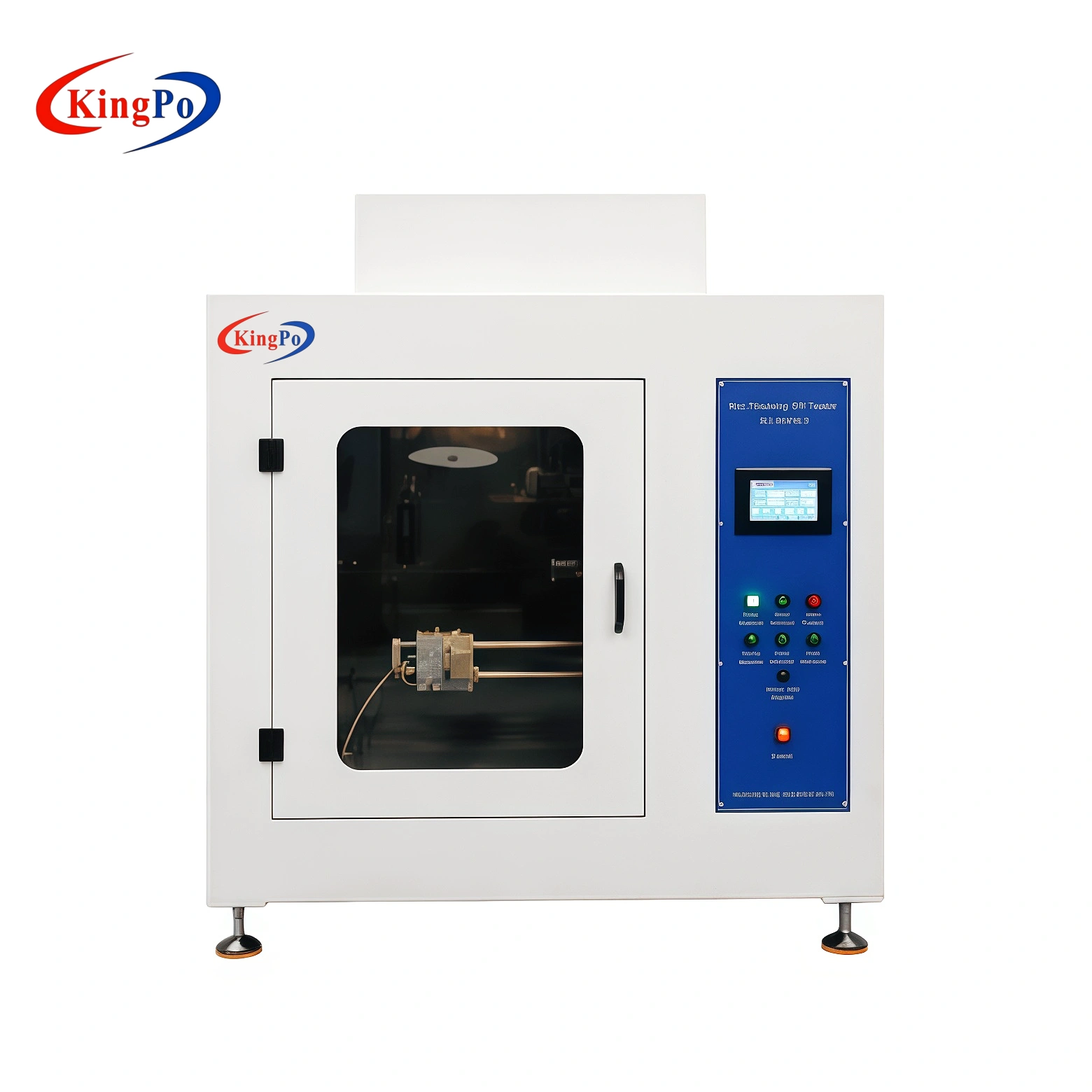
A circuit-integrity system combines thermal exposure, electrical monitoring and, depending on the method, mechanical functions. It should therefore be treated as an integrated test system.
For this reason, a cable circuit-integrity facility is usually better treated as a laboratory engineering project rather than simply another combustion chamber purchase.
Fire, Mechanical Shock and Water Test Scenarios
Real fire conditions can involve more than direct flame exposure. Emergency circuits may need to continue functioning while building structures are subjected to mechanical disturbance or while sprinkler and firefighting systems are operating.
UL’s Abu Dhabi cable laboratory describes capabilities for fire alone, fire with water, fire with mechanical shock, and fire with both mechanical shock and water.
This does not mean that every IEC 60331 test automatically requires water. The actual fire scenario must be determined from the exact IEC, EN, BS, Civil Defense or individual project requirement.
Cable Type
→
Rated Voltage
→
Overall Diameter
→
Core Configuration
→
Fire Condition
→
Mechanical Shock
→
Water Requirement
→
Continuity Monitoring
→
Target Certification
Only after these parameters have been confirmed should the cable fire-resistance test system be specified.
Typical Equipment Map for a Cable Fire Testing Laboratory
| Capability | Standard Family | Main Equipment | Supporting Infrastructure |
|---|---|---|---|
| Single cable flame propagation | IEC 60332-1 | Single Cable Vertical Flame Tester | Gas, ventilation and burner calibration |
| Bunched cable flame spread | IEC 60332-3 | Cable Bundle Flame Propagation System | Large chamber, ladder, airflow, gas and exhaust |
| VW-1 / FT1 | UL 1581 / CSA | VW-1 / FT1 Flame Test Chamber | Gas, timing and exhaust |
| Smoke density | IEC 61034 | Cable Smoke Density Chamber | Optical measurement, extraction and calibration |
| Halogen / corrosive gas | IEC 60754 | Combustion Gas Analysis System | Furnace, gas capture and analytical measurement |
| Circuit integrity | IEC 60331 | Fire Resistance / Circuit Integrity System | Electrical supply, monitoring, gas and exhaust |
| Fire + mechanical shock | Applicable IEC 60331 part | Integrated Fire + Shock System | Impact mechanism, guarding and continuity monitoring |
| Fire + water | Applicable IEC / EN / BS / project method | Integrated Fire + Water Configuration | Controlled water, drainage and electrical protection |
Cable Fire Laboratory Engineering Requirements
The most common mistake in a cable fire laboratory project is to complete the equipment list before the utilities, safety systems and test-room infrastructure have been defined.
1. Combustion Gas and Burner Control
Burner geometry, gas composition, gas pressure, fuel flow, airflow and burner position can directly affect test repeatability. Depending on the test method, the system may require pressure regulation, calibrated flow meters, mass-flow controllers and dedicated flame-verification equipment.
KingPo’s flame and flammability testing equipment range includes burner systems, flame-test apparatus and supporting calibration tools for different fire-test methods.
2. Exhaust and Ventilation
Cable combustion can generate smoke, corrosive gases, toxic products and flaming droplets. Exhaust capacity should therefore be considered during the original laboratory design rather than added after the test equipment has been installed.
Excessive extraction during flame application can alter airflow around the test specimen. The ventilation strategy must protect personnel without invalidating the defined test condition.
3. Electrical Continuity Monitoring
IEC 60331 circuit-integrity testing is not a “burn first, inspect later” test. Electrical performance is monitored while the cable is exposed to thermal and, where applicable, mechanical stress.
For multi-core cable systems, the maximum number of simultaneously monitored conductors should be established before the control and acquisition architecture is selected.
4. Mechanical Shock System
Where mechanical shock forms part of the test method, impact energy, sequence, timing and specimen-support geometry must comply with the applicable standard.
The mechanism must continue to operate reliably in a high-temperature environment without producing unintended cable movement or electrical disconnection unrelated to the required test.
For this reason, the mechanical drive, specimen support, electrical monitoring and safety guarding should be designed as one coordinated system.
5. Water Spray, Water Jet and Drainage
Where water forms part of the referenced method or project specification, water application becomes a controlled test parameter rather than a simple auxiliary function.
Combining energized circuits, an open flame, mechanical impact and water substantially increases the laboratory safety-engineering requirement. Drainage and electrical isolation therefore need to be considered from the beginning of the project.
6. Safety Interlocks
A professional cable fire-test system should coordinate the major safety-related subsystems rather than allow each function to operate independently.
7. Data Acquisition and Test Traceability
Certification laboratories, manufacturer R&D centres and quality-control laboratories performing repeated tests benefit from structured electronic test records instead of recording only a final pass/fail result.
How Engineers Should Specify a Cable Fire Laboratory RFQ
Sending only a list of standard numbers often results in an inaccurate or unnecessarily expensive equipment configuration. A useful RFQ should describe the DUT, required test scenario and available laboratory infrastructure.
IEC, EN, BS, UL, CSA, local Civil Defense requirement or project specification.
Power, control, fire alarm, telecom, data, optical fibre or other cable construction.
Rated voltage, conductor size, number of cores and energized test condition.
Overall diameter, minimum bending radius and required specimen length.
Single flame, bunched flame, circuit integrity, mechanical shock, water or combined conditions.
Number of continuity channels, voltage, current, load and failure-detection method.
Room dimensions, fuel gas, compressed air, exhaust, water, drainage and electrical supply.
Middle East Civil Defense, EU, UK, North America, Africa or another destination market.
Expected number of specimens, test frequency, shift pattern and required automation.
Manual reporting, automatic test record, data export, audit trail or laboratory database integration.
From a Single Tester to a Laboratory-Level Cable Fire Capability
The Middle East example illustrates why cable fire laboratories should increasingly be considered as capability systems rather than collections of unrelated combustion instruments.
Single-Cable Flame Propagation
→
Bunched-Cable Flame Spread
→
Smoke Density
→
Combustion-Gas Behaviour
→
Circuit Integrity
→
Fire + Shock
→
Fire + Water
→
Combined Scenarios
These capabilities use different test methods, measurement principles, utilities and safety systems and should not be treated as interchangeable.
For established flame-propagation methods, KingPo currently provides dedicated IEC 60332 cable flame testing equipment and UL 1581 VW-1 / CSA FT1 flame test chambers.
Related mechanical and durability systems can also be reviewed through the KingPo Cable Testing Equipment range.
For bunched-cable testing, smoke measurement, combustion-gas analysis and IEC 60331 circuit-integrity projects, the equipment scope should be reviewed against the exact test method, specimen construction, electrical conditions and available laboratory infrastructure before the final configuration is confirmed.
Technical Inquiry & Cable Fire Laboratory Configuration Support
For a cable fire testing laboratory project, providing complete DUT and facility information allows the equipment and infrastructure scope to be evaluated more accurately.
KingPo can then review which requirements can be addressed with standard flame-test equipment, which require customized fixtures, electrical monitoring or control systems, and which functions should be considered part of the overall laboratory engineering scope.
Engineering Conclusion
Cable flame propagation, bunched-cable fire spread, smoke production, combustion-gas behaviour and fire-resistant circuit integrity are closely related fire-safety topics, but they are not interchangeable test methods.
For laboratories supporting infrastructure, transportation, emergency systems and international cable markets, the correct engineering sequence is to identify the required fire scenario first, determine the applicable standard and test method second, and only then define the equipment, utility and safety-system requirements.
A cable fire testing laboratory should be designed around the required fire scenario, specimen and compliance objective — not around a single test machine.
Technical References