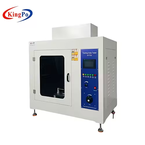
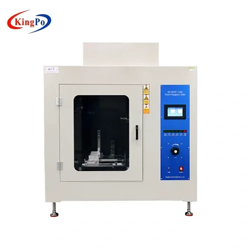
An unsatisfactory glow wire proficiency-testing result does not automatically mean that the glow wire apparatus is defective. Variation can originate from temperature measurement, glow-wire condition, specimen positioning, penetration depth, application force, timing, specimen conditioning, operator judgement or calibration practice.
Effective troubleshooting therefore requires the laboratory to distinguish equipment-related error from method-related, specimen-related and operator-related variation. Replacing components or changing calibration values before identifying the actual failure mechanism can introduce additional uncertainty rather than solve the problem.
Temperature
Verify the complete measurement chain, not only the displayed value.
Glow Wire & Sensor
Inspect wear, contamination, geometry, junction position and connections.
Mechanical Setup
Confirm penetration depth, application force and specimen position.
Method & Operator
Review timing, visual judgement, conditioning and SOP interpretation.
IEC 60695-2-10:2026: What Laboratories Should Review
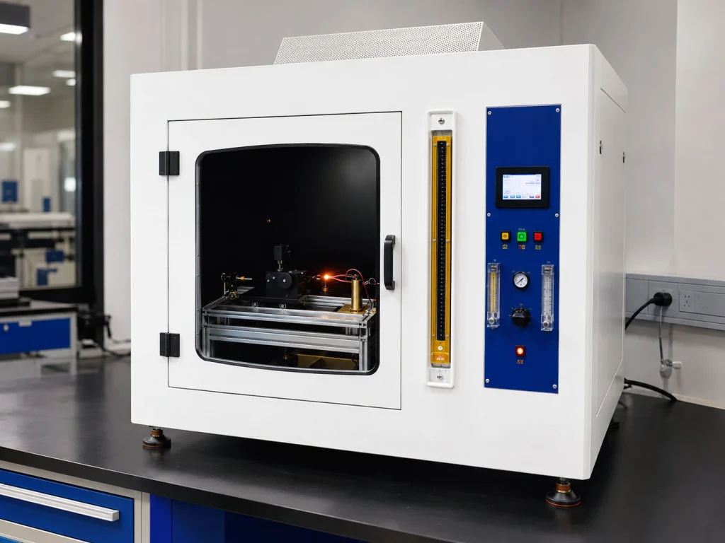
IEC 60695-2-10:2026 is Edition 4.0 of the glow-wire apparatus and common test procedure standard. It replaced the 2021 edition and introduced, among other revisions, a normative Annex D concerning use of a pyrometer in glow-wire testing.
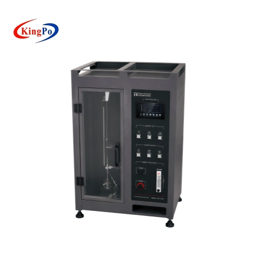
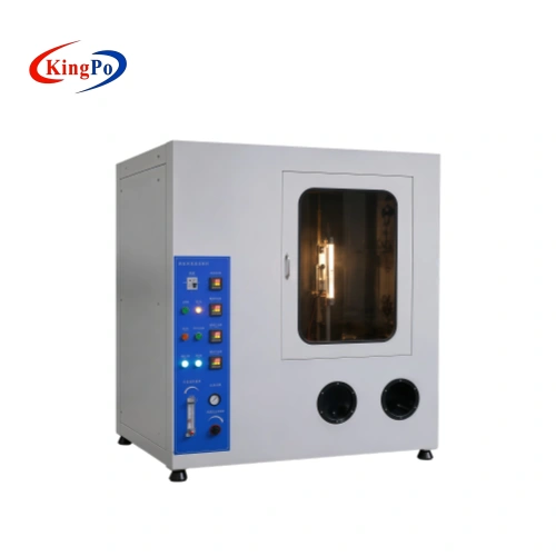
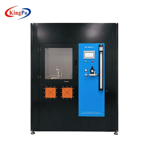
Laboratories should confirm which edition is referenced by their accreditation scope, customer specification or applicable product standard. Equipment configuration, temperature verification and calibration procedures should then be reviewed against that edition. For equipment-level information, refer to the IEC 60695-2-10 glow wire test apparatus page.
Do not assume that an existing calibration procedure automatically demonstrates conformity with a newly adopted standard edition. Review the applicable method, laboratory SOP, calibration records and accreditation requirements first.
What Is Glow Wire Proficiency Testing?
Proficiency testing and interlaboratory comparisons help laboratories evaluate whether their measurement and observation processes produce technically consistent results under defined conditions.
In a glow-wire program, laboratories may receive equivalent or comparable specimens and perform the specified method according to the provider’s instructions. Results are then evaluated using the statistical approach defined by the proficiency-testing provider.
Ignition / non-ignition result
Ignition and extinction observations
Flaming, glowing and extinction
Falling material and underlying layer
A statistical outlier identifies a performance issue that requires investigation. It does not, by itself, prove that the tester, thermocouple or calibration system is the root cause.
Main Sources of Variation in Glow Wire Testing
| Source | Possible Effect | Verification |
|---|---|---|
| Temperature measurement | Incorrect thermal stress | Sensor, indication, calibration and verification method |
| Glow-wire condition | Changed heating or contact geometry | Corrosion, thinning, deformation and residue |
| Thermocouple | Biased or unstable temperature | Junction, placement, connections and calibration |
| Specimen setup | Different thermal exposure | Orientation, fixture and specified application point |
| Penetration / force | Changed mechanical and thermal contact | Travel limit, force mechanism and friction |
| Timing / operator | Different ignition or extinction values | SOP, training, visibility and response |
| Specimen condition | Changed ignition or burning response | Batch, thickness, conditioning and storage |
1. Temperature Measurement and Calibration Errors
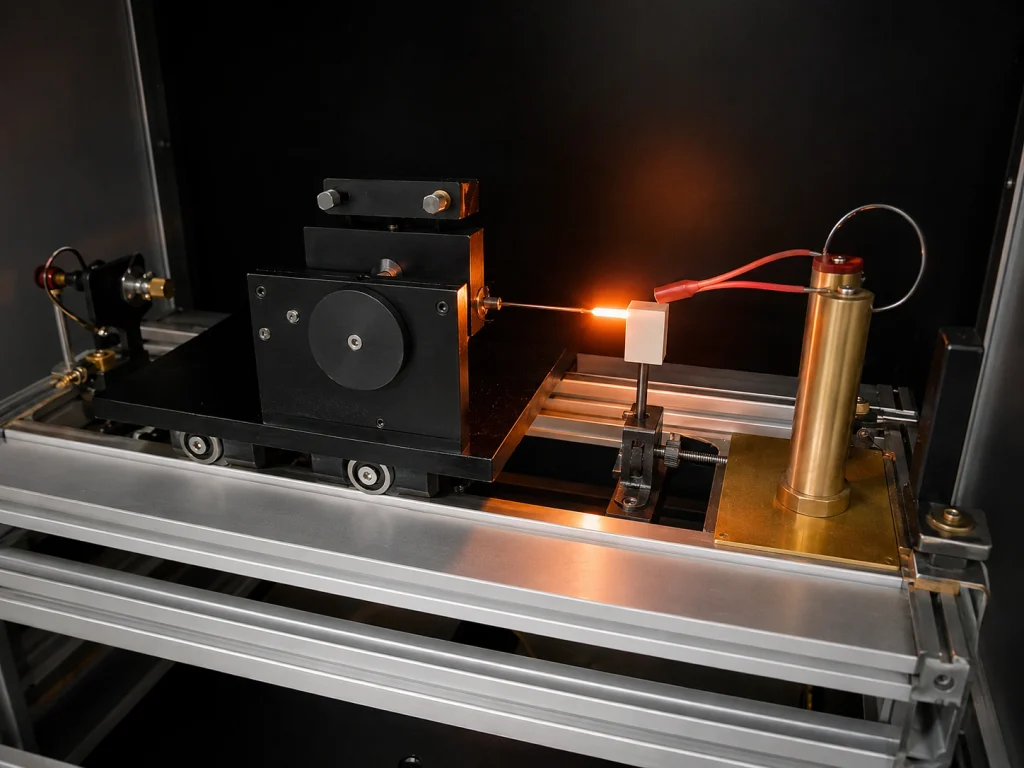
Temperature is one of the most important controlled quantities in glow-wire testing because specimen behaviour depends directly on the thermal stress applied by the heated wire. A displayed value should therefore not automatically be treated as the actual glow-wire temperature.
The laboratory should evaluate the entire measurement chain: thermocouple, measuring junction, wiring, temperature indicator, calibration data and any independent verification method.
Temperature takes much longer than normal to reach equilibrium.
Displayed temperature fluctuates more than expected.
Previously stable current-to-temperature behaviour changes.
Independent verification disagrees with the instrument indication.
Do not immediately alter calibration offsets. First determine whether the deviation comes from the thermocouple, glow wire, connections, temperature indicator or reference system.
2. Thermocouple Condition and Placement
The thermocouple is part of the temperature-measurement system and should be treated as a precision component rather than simply as a replaceable wire. Junction condition, mounting position and electrical connections can all influence the indicated temperature.
Investigation is appropriate when the sensor is physically damaged, the measuring junction moves, the temperature/current relationship changes unexpectedly or reference verification indicates an unacceptable deviation. Laboratories that manufacture or repair fine-wire junctions can also review the thermocouple wire welder used for fine junction preparation.
3. Glow-Wire Condition, Corrosion and Geometry
Repeated high-temperature cycles can change the surface and geometry of the glow-wire element. Oxidation, corrosion, contamination, thinning or deformation may alter both heating behaviour and contact with the specimen.
Visible thinning
Corrosion / oxidation
Mechanical deformation
Surface residue
Cracks / damage
Cleaning should remove test residue without damaging the temperature sensor or changing the intended geometry. If the element no longer supports repeatable testing, replacement is preferable to repeatedly compensating through calibration adjustments.
4. Penetration Depth, Application Force and Specimen Position
Mechanical setup directly influences heat transfer. Excessive travel or force increases contact and specimen deformation, while insufficient contact reduces thermal coupling.
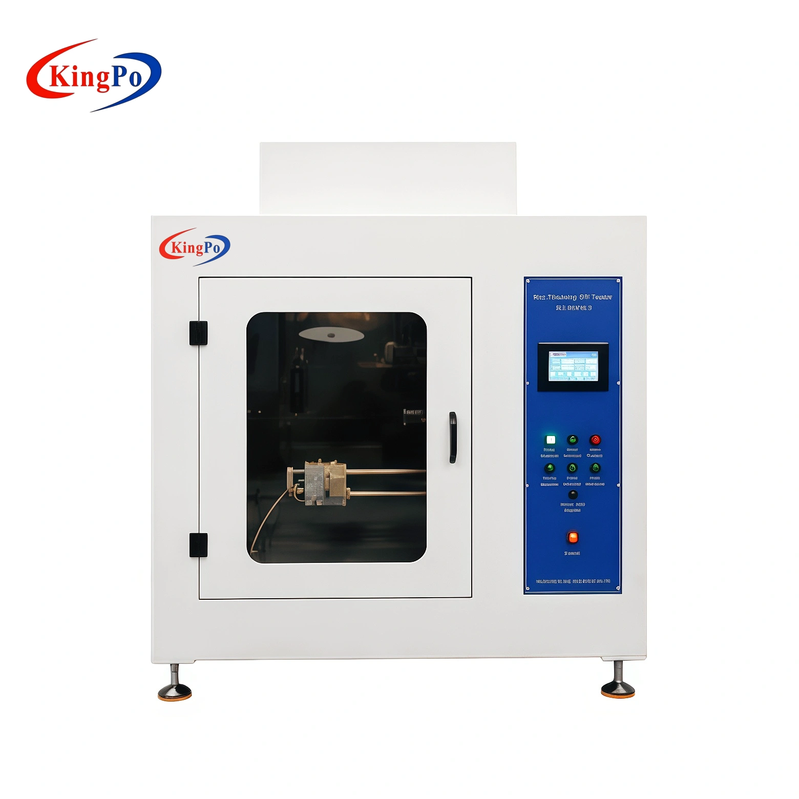
During troubleshooting, check the mechanical limit, carriage movement, friction, fixture alignment and specimen application point. Machine-specific adjustment should follow the KP-FT01 operating procedure.
5. Timing and Operator Observation
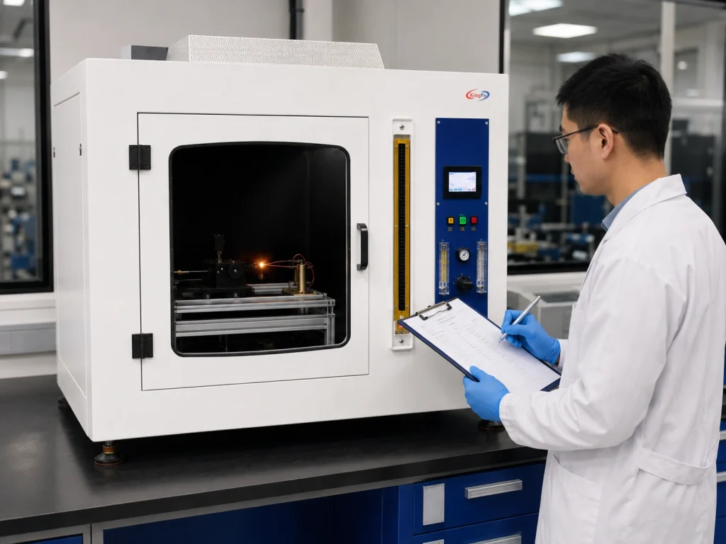
Timing errors can occur even when equipment temperature and mechanics are correct. Operator interpretation becomes especially important when ignition, weak glowing or extinction events must be identified visually.
Specified contact duration.
Ignition-related timing according to the method.
Extinction-related timing according to the method.
When operator-to-operator differences occur, review SOP definitions, visibility, lighting, response time and whether weak flaming or glowing is interpreted consistently.
6. Specimen Conditioning and Material Variability
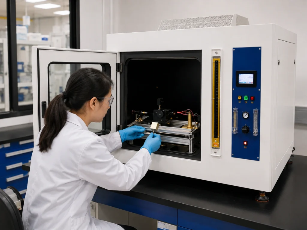
Not every laboratory difference is equipment-related. Polymer formulation, moisture, specimen thickness, moulding history, ageing, surface condition, batch and orientation can all influence ignition and burning behaviour.
Conditioning
Thickness
Orientation
Application point
Storage
7. Laboratory Environment and Exhaust Operation
Air movement can affect cooling, flame behaviour and visual observation. Strong airflow across the test zone should therefore be avoided unless required by the applicable method.
Exhaust should remove combustion products safely without disturbing the actual test condition. The test system should also be installed on a stable level surface with adequate ventilation, clearance and laboratory fire-safety provisions.
8. Measurement Uncertainty in Glow Wire Testing
Measurement uncertainty should reflect the laboratory’s own measurement process rather than a generic value copied from another organization. Potential contributors include temperature calibration, indication resolution, stability, force, penetration depth, timing, operator judgement, specimen variability and reference-equipment uncertainty.
An example uncertainty budget can be used to understand methodology, but the reported uncertainty must represent the laboratory’s actual equipment, calibration data, procedure and conditions.
9. Root Cause Analysis After an Unsatisfactory PT Result
Check transcription, calculations and submitted results.
Check what the operator actually observed and recorded.
Review calibration and intermediate checks on the test date.
Review glow wire, thermocouple, fixture and carriage.
Check temperature, time, force, depth and specimen setup.
Determine whether the abnormal behaviour is repeatable.
KP-FT01 Troubleshooting Matrix
| Symptom | Likely Area | Recommended Check |
|---|---|---|
| No heating | Heating circuit / glow wire | Inspect element, terminals and connections with power isolated |
| Unstable temperature | Sensor / heating system | Inspect thermocouple, element and verification data |
| Unexpected ignition | Temperature / specimen / mechanics | Review complete setup before repeating the test |
| Different Ti / Te | Operator / SOP | Compare definitions, visibility and operator response |
| Excessive travel | Mechanical limit | Repeat penetration-depth setup |
| Residue on glow wire | Previous specimen deposits | Clean carefully without altering geometry |
Pre-Test Verification Checklist
Practical KP-FT01 Test Sequence
| 01 | Set the required glow time and test parameters. |
| 02 | Prepare the underlying material arrangement where required. |
| 03 | Clamp and position the specimen. |
| 04 | Set and verify the mechanical penetration limit. |
| 05 | Heat the glow wire to the required temperature and stabilize. |
| 06 | Start the test cycle and observe ignition behaviour. |
| 07 | Record required timing and visual observations. |
| 08 | After testing, remove combustion products and clean the test area. |
This sequence is only an operating overview. Machine-specific control functions and mechanical adjustments should follow the official KP-FT01 operation document and the applicable glow-wire test method.
Routine Maintenance and Verification
Corrosion, thinning, contamination and geometry.
Junction condition, connection and response.
Calibration and intermediate verification.
Movement, alignment, friction and mechanical limit.
Function, repeatability and resolution.
Residue, visibility and extraction operation.
How This Differs from Other Electrical Safety Tests
Glow-wire troubleshooting should not be confused with troubleshooting insulation resistance, dielectric strength or leakage-current measurements. Glow-wire methods evaluate fire behaviour caused by abnormal thermal stress, whereas electrical insulation tests evaluate different hazards and measured quantities. See Glow Wire vs Insulation Resistance, Hipot and Needle Flame Tests for the engineering distinction.
Key Takeaways
Verify the complete measurement chain before adjusting calibration.
Depth, force, friction and specimen position affect heat transfer.
An outlier requires investigation but does not identify the cause.
Visual judgement and timing can create inter-operator variation.
Frequently Asked Questions
1. Why do two laboratories obtain different glow wire results?
Differences can arise from temperature measurement, glow-wire condition, penetration depth, application force, specimen conditioning, operator judgement, timing and environmental influences.
2. Does an unsatisfactory PT result mean the tester is inaccurate?
No. It indicates that the laboratory result requires investigation. The root cause may involve equipment, method execution, specimens, operator factors or environmental conditions.
3. What should be checked first after a glow wire PT failure?
Confirm the reported result and raw records first. Then review temperature verification, calibration status, glow-wire condition, thermocouple condition, mechanical settings and specimen preparation.
4. How important is temperature calibration?
Temperature defines the thermal stress applied to the specimen. The laboratory should therefore maintain suitable calibration and verification of the complete temperature-measurement system.
5. Can thermocouple condition affect the result?
Yes. Junction deterioration, mechanical damage, incorrect placement, connection problems and ageing can alter temperature indication and stability.
6. Why is penetration depth important?
Penetration controls mechanical contact between the specimen and heated wire. Incorrect travel changes contact conditions and therefore heat transfer.
7. Can operator judgement affect Ti and Te?
Yes. Visibility, training, SOP wording and reaction time can all influence visually determined ignition and extinction events.
8. Should calibration be adjusted immediately after a PT failure?
Not without evidence. Adjustment before root-cause identification can hide another problem or introduce a new systematic bias.
9. What changed with IEC 60695-2-10:2026?
Edition 4.0 introduced technical revisions including a normative Annex D related to use of a pyrometer. Laboratories should compare the new edition with their existing SOP and calibration approach.
10. Where can I find the KP-FT01 operating procedure?
KingPo provides a dedicated operation document covering installation, component replacement, mechanical adjustment and test operation. It is linked naturally in the mechanical and operating sections above.
Investigating an Abnormal Glow Wire Result?
For technical review, provide the applicable standard and edition, test method, temperature, specimen material and thickness, observed result, temperature verification data, glow-wire and thermocouple condition, and photos of the test setup where available.
KingPo can review equipment configuration and operating conditions to help identify likely equipment-related causes. Final interpretation of proficiency-testing, accreditation or compliance results remains the responsibility of the laboratory and applicable conformity-assessment body.
.