DENG Sha¹, ZHANG Chao², WU Shaohai¹ Corresponding author: FAN Xiang¹
- Guangdong Institute of Medical Device Quality Supervision and Inspection, No. 1 Guangpu West Road, Huangpu District, Guangzhou, Guangdong 510663, China
- KingPo Technology Development Limited, No. 9 University Road, Songshan Lake, Dongguan, Guangdong 523869, China
Abstract: When existing electrosurgery analyzers are used to measure the output power, voltage and current of 4 MHz high-frequency electrosurgical units, problems such as insufficient data repeatability, large differences among test instruments and unstable judgment of rated output power are often observed. Conventional analysis usually attributes these problems to insufficient sampling bandwidth, RMS algorithm error or calibration-frequency mismatch of the analyzer. For 4 MHz electrosurgical units, however, the root cause of the test error does not lie only in the measuring instrument itself. It is also closely related to the non-ideal electromagnetic characteristics of the rated load resistance under high-frequency, high-power excitation. This paper analyzes the distortion mechanism of the rated load resistance in 4 MHz testing from three perspectives: resistor skin effect, resistor structural form and radiation coupling in the test loop under strong electrosurgical excitation. The study indicates that the conventional assumption that the rated load resistance is an ideal pure resistance is not sufficiently valid at 4 MHz. Affected by skin effect, the AC equivalent resistance may deviate from the DC nominal value. Affected by resistor geometry, lead structure, mounting method and heat-dissipation structure, the load may introduce parasitic inductance and parasitic capacitance. Under high-voltage, high-current, non-sinusoidal or pulse-modulated output excitation, the test loop may also generate significant electromagnetic radiation, near-field coupling and additional power loss. IEC 60601-2-2 is the particular standard for the basic safety and essential performance of high-frequency surgical equipment and high-frequency surgical accessories. Output power testing of electrosurgical units is generally performed under specified load conditions or under the manufacturer-declared rated load. Therefore, the authenticity and repeatability of the load condition directly affect the reliability of the test conclusion. This paper proposes that the rated load resistance used in 4 MHz electrosurgical unit testing should be transformed from a conventional DC nominal-resistance model into a high-frequency composite electromagnetic load model that comprehensively considers skin effect, parasitic parameters, thermal drift and radiation coupling. To improve measurement accuracy, low-inductance non-inductive loads or coaxial RF loads, 4 MHz impedance calibration of the rated load, controlled test-loop area and radiation coupling, synchronous voltage-current sampling and instantaneous power integration for active power calculation are recommended.
Keywords: 4 MHz electrosurgical unit; rated load resistance; skin effect; resistor form; radiation coupling; IEC 60601-2-2; electrosurgery analyzer; output power testing
Chinese Library Classification No.: R318.6 Document code: A DOI: to be completed by the editorial office
Manuscript received: to be completed by the editorial office. Author biography: DENG Sha, email: ; Corresponding author: FAN Xiang, email: .
1 Introduction
The output power of a high-frequency electrosurgical unit is directly related to cutting performance, coagulation effect and patient safety [1]. Compared with conventional electrosurgical units, 4 MHz devices are more easily affected by load impedance, connecting cables and fixture structures. Previous studies have shown that MHz-level load impedance, dynamic compensation and waveform acquisition can influence power measurement [2-4]. IEC 60601-2-2 and JJF 1217-2025 both emphasize rated-load and operating-frequency conditions [5,7]. This paper analyzes the influence of skin effect, parasitic parameters and radiation coupling on the accuracy of 4 MHz output power testing. The research logic is shown in Fig. 1.

Fig. 1 Schematic pathway of output power test error formation in a 4 MHz electrosurgical unit
2 Rated-Load Testing Issues Under IEC 60601-2-2
IEC 60601-2-2 is a particular standard for the basic safety and essential performance of high-frequency surgical equipment and high-frequency surgical accessories. Under this standard framework, output performance testing of electrosurgical units usually needs to be completed under specified loads or under the manufacturer-declared rated load. The 0.3-5.0 MHz operating-frequency range covered by JJF 1217-2025 also indicates that 4 MHz output power testing is already within the core frequency band of high-frequency calibration practice [7].
For a high-frequency electrosurgical unit, the rated load is not merely a test accessory; it is an essential condition defining the output state of the equipment. For example, if a device declares an output of 100 W under a 500 Ω load, the 500 Ω load is not simply a denominator in a power-calculation formula. It forms part of the rated output operating point of that electrosurgical unit. If the so-called 500 Ω load actually behaves as 500 Ω + jX at 4 MHz, or if its impedance magnitude and phase angle change with temperature rise and wiring method, the device under test is no longer operating under the ideal rated-load condition.
The traditional test model usually assumes that the load resistor is an ideal pure resistor, that voltage and current are in phase, and that all output power is absorbed by the load. The model can be written as:
P = U^2 / R or P = I^2R
where R is regarded as an ideal pure resistance. For a 4 MHz electrosurgical unit, however, this model implicitly assumes that the load resistance at 4 MHz remains equal to its DC nominal value, that the load does not have significant parasitic inductance or parasitic capacitance, that voltage-current phase difference can be ignored, that the test loop does not generate significant electromagnetic radiation, and that the output power is almost entirely dissipated in the load resistor.
In actual testing, these assumptions are often difficult to satisfy completely. Therefore, the output power test of a 4 MHz electrosurgical unit should be transformed from an “ideal load test” into a “high-frequency composite-load test”, as shown in Fig. 2.

3 Influence of Resistor Skin Effect on the Rated Load
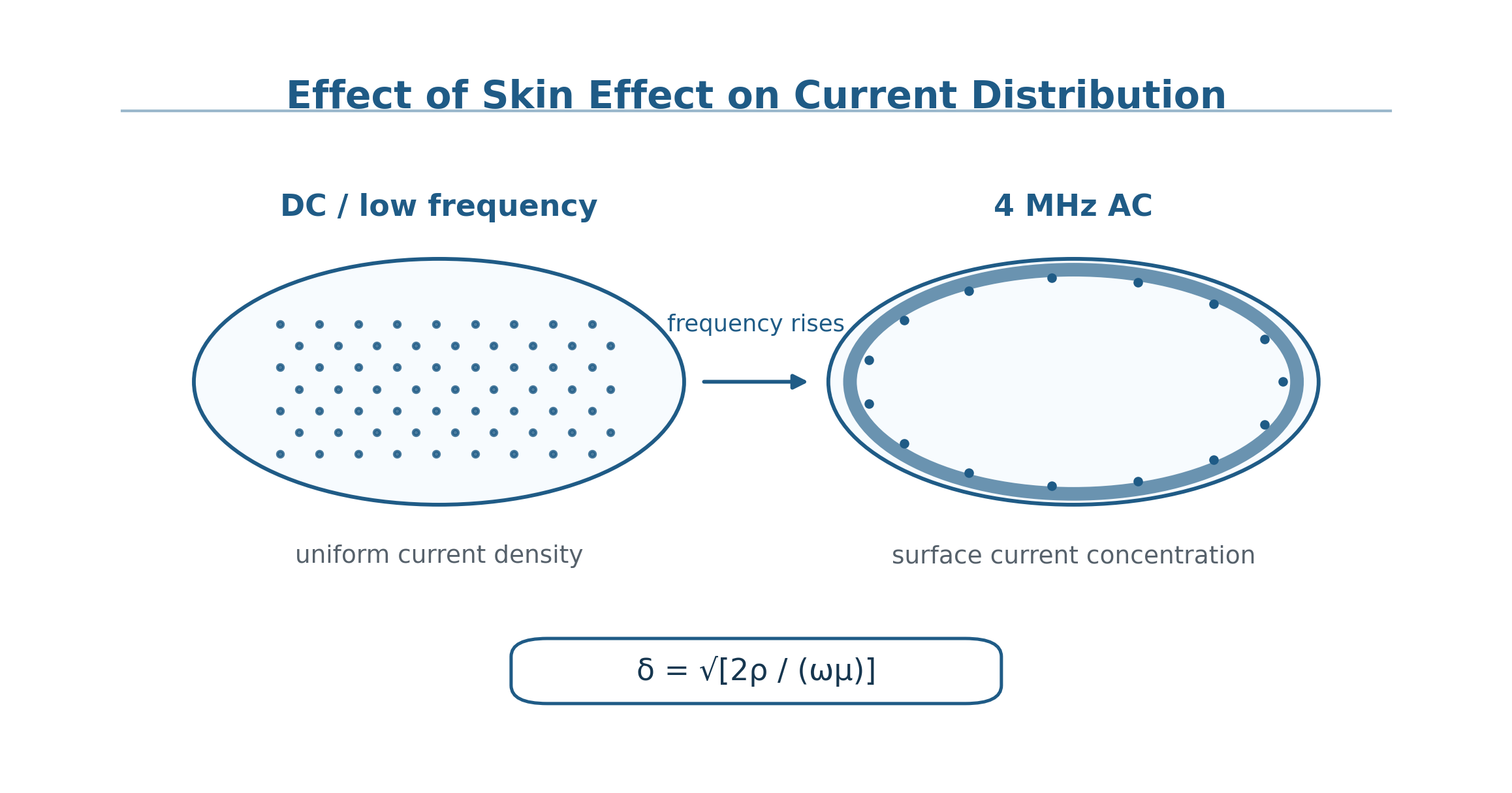
3.1 Basic Mechanism of Skin Effect
Skin effect refers to the phenomenon in which, when alternating current passes through a conductor, the current gradually concentrates near the conductor surface as frequency increases, reducing the current density inside the conductor. As a result, the effective conductive cross-sectional area decreases and the AC resistance becomes higher than the DC resistance. Skin depth can be expressed as:
δ = sqrt[2ρ / (ωμ)]
where δ is the skin depth, ρ is material resistivity, ω is angular frequency, μ is material permeability, and ω = 2πf. When the frequency rises to 4 MHz, current distribution is already significantly different from the DC condition. For metal terminals, connecting plates, resistive film layers, leads and conductive structures in high-power load resistors, skin effect changes the current distribution and therefore changes the AC equivalent resistance. If the DC nominal resistance alone is used as the basis for power calculation, the influence of frequency-dependent resistance on load power absorption will be ignored.

3.2 Difference Between DC Nominal Resistance and High-Frequency AC Resistance
Under DC conditions, the rated load resistance can be expressed as R = Rdc, where Rdc is the DC nominal resistance. Under 4 MHz high-frequency conditions, however, the rated load should be expressed as R = Rac(f), where Rac(f) is the frequency-dependent AC equivalent resistance. Due to skin effect, proximity effect and conductor structure, Rac is often not equal to Rdc.
After further considering parasitic parameters, the load should be expressed as:
Zload(f) = Rskin(f) + jX(f)
where Rskin(f) is the equivalent resistance component affected by skin effect, and X(f) is the reactance component jointly formed by parasitic inductance and parasitic capacitance. This means that a nominal 500 Ω load may not still be equivalent to a pure 500 Ω resistance at 4 MHz. If an electrosurgery analyzer still calculates power according to an ideal 500 Ω load, systematic error will occur.
Therefore, the rated-load label should not only provide a DC nominal value such as “500 Ω”. It should also provide the impedance magnitude at 4 MHz, phase angle, temperature-rise drift at rated power and recommended connection method. For load modules used in type testing or third-party inspection, frequency-sweep records should also be retained to support traceability and repeatability of test results.
3.3 Influence of Skin Effect on Power Testing
Under ideal conditions, P = U^2 / Rdc. Under high-frequency conditions, P = U^2 / Rac. If Rac > Rdc, then under the same voltage, the actual power absorbed by the load will be smaller than the power calculated using Rdc. If the analyzer cannot identify this change, the displayed power may be higher than the actual active power. At the same time, a high-frequency electrosurgical unit itself is not an ideal voltage source. Changes in load resistance feed back into the operating point of the output stage, causing output voltage, current and power to change. Therefore, skin effect affects not only power calculation, but also the actual output state of the sample under test.
4 Influence of Resistor Form on Parasitic Parameters
4.1 Decisive Role of Resistor Form in High-Frequency Characteristics
In low-frequency or DC testing, resistors of different structural forms can usually be regarded as functionally similar as long as their nominal resistance values are the same. In 4 MHz high-frequency testing, however, resistor form directly determines high-frequency behavior. Wirewound resistors, cement resistors, metal-film resistors, thick-film non-inductive resistors and coaxial RF loads with the same nominal resistance may show completely different impedance magnitudes, phase angles and stability at 4 MHz.
Table 1 Comparison of high-frequency characteristics of different resistor forms at 4 MHz
| Resistor form | Major high-frequency issue | Influence on electrosurgical unit testing | Recommendation |
| Wirewound resistor | Significant parasitic inductance | The load becomes inductive and the voltage-current phase difference increases. | Not recommended |
| Cement resistor | Long leads and large temperature rise | Resistance drift occurs and repeatability decreases. | Use with caution |
| General high-power resistor | Complex structure and uncertain parasitic parameters | Different batches and mounting methods may cause significant differences. | Use with caution |
| Metal-film resistor array | Good high-frequency performance but limited power capacity | Suitable for low-power testing or multi-resistor parallel design. | Optional |
| Thick-film non-inductive resistor | Low inductance and compact structure | More suitable as a high-frequency test load. | Recommended |
| Coaxial RF load | Defined return path and low radiation | Suitable as a high-frequency reference load. | Preferred |

4.2 Sources and Influence of Parasitic Inductance
Parasitic inductance mainly comes from the coil structure of wirewound resistors, resistor leads, load connection wires, fixtures and terminals, PCB traces, load-loop area, and current paths in heat sinks and mounting structures. The inductive reactance is:
XL = 2πfL
At 4 MHz, even a small parasitic inductance can significantly affect the test result. For example, when additional inductance exists in the load loop, the load no longer behaves as a pure resistance but shows inductive characteristics. A phase difference is generated between voltage and current. If the analyzer still calculates power using the pure-resistance model, the influence of reactive power on the reading will be ignored.
4.3 Sources and Influence of Parasitic Capacitance
Parasitic capacitance mainly arises between the resistor body and heat sink, between resistor terminals, between the resistor and metal enclosure, between the output terminal and ground, between PCB copper foils, and between cables and surrounding metal structures. The capacitive reactance is:
XC = 1 / (2πfC)
At 4 MHz, parasitic capacitance may provide a bypass path for high-frequency current, so that part of the current no longer flows completely through the ideal load resistor. This results in a load-current distribution inconsistent with the theoretical model, and also causes the voltage and current signals acquired by the electrosurgery analyzer to fail to accurately represent the active power absorbed by the load resistor.
4.4 Transformation of the Rated Load into an RLC Network Due to Resistor Form
In summary, under 4 MHz high-frequency conditions, the rated load should no longer be simply expressed as Zload = R. It should be expressed as:
Zload = Rskin + jωLparasitic + 1/(jωCparasitic)
where Rskin represents the AC resistance affected by skin effect, Lparasitic represents parasitic inductance introduced by structure and connections, and Cparasitic represents parasitic capacitance formed by the resistor, heat-dissipation structure, cables and surrounding environment.
5 Radiation Coupling Under Strong High-Frequency Electrosurgical Excitation
5.1 Electrosurgical Testing Is Not Small-Signal Impedance Testing
When an impedance analyzer or vector network analyzer measures the high-frequency characteristics of a resistor, it usually uses small-signal excitation. In actual electrosurgical testing, however, the load operates under high-voltage, high-current, high-power and non-sinusoidal waveform excitation. Especially in coagulation and spray-coagulation modes, the output may include pulse modulation, high peak voltage and large transient variations. Therefore, the operating state of the load in actual electrosurgical testing differs significantly from that under small-signal impedance-test conditions.
5.2 Formation Mechanism of Test-Loop Radiation
When the electrosurgical unit output is connected to a load, the output wire, return wire, load resistor, fixture and analyzer jointly form a high-frequency current loop. If the loop area is large, the path is asymmetric or the connection wires are long, the loop may exhibit radiation behavior similar to an antenna. Radiation coupling mainly originates from excessive high-frequency current-loop area, excessive separation between output and return conductors, long load wires, open conductor structures, unshielded loads, near-field coupling into sampling wires and changes in electromagnetic-field distribution caused by surrounding metal structures. From the perspective of electromagnetic compatibility, this type of open high-frequency loop increases near-field coupling and radiation susceptibility [9].

5.3 Influence of Radiation Coupling on Power Balance
Ideally, all output power from the electrosurgical unit is dissipated in the load resistor:
Pout = Pload
When obvious radiation and coupling exist in the test loop, the power balance should be expressed as:
Pout = Pload + Pradiation + Pcoupling + Ploss
where Pload is the actual power absorbed by the load resistor, Pradiation is the radiation loss of the test loop, Pcoupling is the power coupled into the analyzer enclosure, sampling cable, grounding structure or nearby metal bodies, and Ploss is the additional loss of cables, connectors, terminals and other structures.
5.4 Influence of Radiation Coupling on Test Repeatability
Radiation coupling makes test results highly sensitive to environmental and operating conditions. For the same electrosurgical unit, the same power setting and the same nominal load, different results may appear when output-cable length, cable bending mode, distance between load and analyzer, load placement, grounding method, operator hand proximity, nearby metal table position and the presence or absence of shielding structures are changed.
6 Influence of Rated-Load High-Frequency Distortion on the Operating Point of the Device Under Test
A high-frequency electrosurgical unit is neither an ideal voltage source nor an ideal current source. Its output power has matching and regulation relationships with load impedance. When the rated-load impedance changes, the actual output state of the device under test changes accordingly.
For a declared rating of 100 W / 500 Ω / 4 MHz, the ideal test condition is Zload = 500 Ω. In actual testing, due to skin effect, parasitic parameters and radiation coupling, the load may behave as:
Zactual = 520 Ω + j40 Ω
At this point, the load seen by the device under test is no longer a pure 500 Ω resistance. This may cause the output voltage of the electrosurgical unit to increase or decrease, the output current to change, the matching state of the output stage to shift, the actual active power to differ from the power under nominal rated-load conditions, and the analyzer displayed power to be inconsistent with the true load-absorbed power. Ultimately, it affects the basis for judging rated output power under IEC 60601-2-2.
It should be noted that the error caused by load shift has a dual nature. On the one hand, the readings obtained by the voltage and current sampling chain deviate from the true active power. On the other hand, the power regulation or matching state of the device under test changes. Therefore, subsequent error analysis should not only correct the analyzer display value, but also confirm whether the sample under test remains at the declared rated-load operating point.

7 Comprehensive Equivalent Model
To describe the 4 MHz electrosurgical test system more accurately, the rated load resistance can be modeled by reference to the complex-impedance modeling approach used in high-frequency engineering. The rated load can be treated as a composite electromagnetic load jointly affected by frequency, power, temperature and geometry [10]:
Zactual(f, P, T, G) = Rdc + ΔRskin(f) + ΔRthermal(P,T) + jωLparasitic(G) + 1/(jωCparasitic(G)) + Zradiation(f,G)
where f is the operating frequency, P is the output power, T is the load temperature, and G is the resistor geometry and test-loop structure. Rdc is the DC nominal resistance; ΔRskin(f) is the AC resistance change caused by skin effect; ΔRthermal(P,T) is the resistance drift caused by power and temperature rise; Lparasitic(G) is the parasitic inductance caused by structure and connection; Cparasitic(G) is the parasitic capacitance caused by structure and environment; and Zradiation(f,G) is the equivalent term for radiation coupling.
The actual active power should be calculated using instantaneous power integration:
Pactive = (1/T) ∫0^T u(t)i(t)dt
For non-sinusoidal, modulated and pulsed waveforms, this method is more reasonable than a simple U^2/R calculation because it considers voltage and current waveforms as well as phase relationship. The comprehensive equivalent model is shown in Fig. 7.
In engineering implementation, a high-frequency LCR meter or vector network analyzer can be used to scan impedance at 1, 2, 3, 4 and 5 MHz, extract parameters such as R, Lp and Cp, and establish a load database. In 4 MHz power testing, this database can then be combined with synchronous voltage-current sampling results to correct the effects of complex impedance and phase difference on active-power calculation [3]. At the same time, studies of oscilloscope-based electrosurgery analyzers show that high-bandwidth waveform acquisition can be used to observe output waveform, frequency and power parameters synchronously, thereby supporting power evaluation for non-sinusoidal or pulse-modulated outputs [4].

8 Experimental Verification Scheme
8.1 4 MHz Impedance Testing of Different Resistor Forms
The purpose of this experiment is to verify whether different resistor forms with the same nominal resistance show impedance differences at 4 MHz. Test objects include wirewound power resistors, cement resistors, general high-power resistors, metal-film resistor arrays, thick-film non-inductive resistors and coaxial RF loads. Test parameters include DC resistance Rdc, 4 MHz impedance magnitude |Z|, 4 MHz phase angle θ, equivalent series resistance ESR, equivalent series inductance ESL, equivalent parallel capacitance EPC and impedance changes before and after heating.

8.2 Load Drift Testing Under Strong High-Frequency Electrosurgical Excitation
The purpose of this experiment is to verify whether the load changes dynamically under actual strong excitation from a 4 MHz electrosurgical unit. The proposed method is to set the electrosurgical unit to typical output modes, connect different forms of 500 Ω load or the manufacturer-declared rated load, record load temperature and impedance changes before output and after 10 s, 30 s and 60 s of output, and compare power-reading drift among different load structures.

8.3 Test-Loop Radiation Coupling Experiment
The purpose of this experiment is to verify the influence of test-loop radiation and coupling on power readings. Variables include output-wire length, distance between output and return conductors, ordinary wire/twisted pair/coaxial cable, open load/shielded load, distance between load and analyzer, grounding method and near-field-probe monitoring conditions. Recorded parameters include analyzer displayed power, voltage waveform, current waveform, phase difference, near-field radiation intensity, repeatability error and instantaneous power-integration result.

8.4 Verification Experiment for Optimized Load Structure
The purpose of this experiment is to verify whether low-inductance, coaxial and shielded design can improve test accuracy. Four schemes can be compared: ordinary wire plus ordinary resistor, short wire plus non-inductive resistor, coaxial connection plus non-inductive load, and coaxial RF load plus shielding structure. Evaluation indicators include power error, repeatability, phase angle, load temperature rise and near-field radiation intensity.
8.5 Verification of Impedance Scanning and Dynamic Compensation
The purpose of this experiment is to verify whether high-frequency impedance characterization and dynamic compensation improve power-test accuracy. A 500 Ω precision reference load and different structural loads can be selected for impedance-magnitude, phase-angle and temperature-drift testing in the 1-5 MHz band. Synchronous voltage-current sampling can then be performed at 4 MHz under typical output-power conditions to compare power readings, phase error and repeatability before and after compensation. The synchronous sampling part can be combined with the oscilloscope-analyzer concept to record non-sinusoidal waveforms, pulse-modulated waveforms and high-crest-factor waveforms at the waveform level. The experiment should not use a single power reading as the sole criterion; load placement, cable path, grounding method and shielding conditions should also be recorded.
9 Optimization Recommendations for the Test System
9.1 Rated Loads Should Be Calibrated at 4 MHz
For a 4 MHz high-frequency electrosurgical unit, the rated load resistor should not only provide DC resistance calibration results. It should also provide high-frequency parameters at the operating frequency, including 4 MHz impedance magnitude, 4 MHz phase angle, equivalent series resistance, equivalent series inductance, equivalent parallel capacitance, temperature-rise drift at rated power, measurement uncertainty and recommended wiring method.
Recommended labeling: 500 Ω, |Z| at 4 MHz = xxx Ω, phase angle = xx°, rated power = xxx W, temperature-rise drift = xx%, uncertainty = xx%.
9.2 Low-Inductance Non-Inductive or Coaxial Loads Are Preferred
Wirewound resistors and high-power resistors with unclear structure should be avoided for 4 MHz electrosurgical testing. Recommended options include thick-film non-inductive resistors, metal-film low-inductance resistor arrays, coaxial RF loads, oil-cooled or water-cooled non-inductive loads, low-loop-area load structures and shielded load modules.
9.3 Radiation Coupling in the Test Loop Should Be Controlled
It is recommended that the output and return conductors be kept as close as possible, coaxial connection be preferred, cable length be reduced, large-area open loops be avoided, the load module use a metal-shielded enclosure, sampling wires be separated from or shielded from power lines, grounding be standardized, cable positions be fixed, and near-field probes be used when necessary to monitor test-loop radiation. The optimized system structure is shown in Fig. 11.

9.4 Instantaneous Power Integration Should Be Used for Power Calculation
For a 4 MHz electrosurgical unit, especially in modulated-output and pulsed-output modes, it is not recommended to rely solely on P = U^2/R. A more reasonable method is to synchronously acquire voltage and current waveforms and calculate Pactive = (1/T)∫u(t)i(t)dt. This method can account for phase difference, non-sinusoidal waveforms and transient variations, and is more suitable for evaluating the actual output power of a high-frequency electrosurgical unit.
9.5 Summary of Test-Error Sources and Load Applicability
Table 2 Summary of error sources in output power testing of 4 MHz electrosurgical units
| Error source | Specific manifestation | Influence on result |
| Skin effect | Rac deviates from Rdc | Power-calculation deviation |
| Parasitic inductance | Current lags and reactance increases | Phase error and power deviation |
| Parasitic capacitance | High-frequency bypass current | Changed current distribution |
| Thermal drift | Resistance changes over time | Reduced repeatability |
| Radiation coupling | Energy couples into space or enclosures | Data fluctuation and environmental sensitivity |
| Strong-excitation nonlinearity | Small-signal measurements cannot represent actual operating conditions | Distortion of rated-load condition |
| Analyzer algorithm | RMS or U^2/R model simplification | Increased error under non-sinusoidal waveforms |
9.6 Test Reports Should Record Equivalent Load Conditions
It is recommended that the test report additionally record the DC resistance of the rated load, 4 MHz impedance magnitude, phase angle, connection-wire length, shielding method, load temperature rise and calibration date. For modulated or pulsed output modes, the report should also specify whether the power calculation uses a true-RMS model, a U^2/R model or a synchronous voltage-current integration model. These records help compare results among different laboratories, different electrosurgery analyzers and different load structures.
10 Discussion
The core viewpoint of this paper is that test error in 4 MHz electrosurgical units cannot be simply attributed to insufficient accuracy of the electrosurgery analyzer. Under high-frequency, high-power excitation, the rated load resistor in the test system has become a key factor affecting test results. Compared with existing dynamic-compensation studies and oscilloscope-based analyzer studies, this paper places greater emphasis on the coupling relationship among the load itself, the test loop and the operating point of the device under test, and treats load equivalence as a prerequisite for accurate power testing.
First, skin effect causes the AC equivalent resistance of the resistor to deviate from its DC nominal value. For 4 MHz high-frequency output, current distribution is no longer uniform, and resistor terminals, connecting plates and resistive film layers may all generate AC resistance changes. Second, resistor form determines parasitic parameters. Wirewound resistors, cement resistors, thick-film resistors and coaxial loads may have the same DC resistance, but their phase angles, impedance magnitudes and radiation characteristics at 4 MHz differ significantly. Therefore, identical nominal resistance does not mean identical high-frequency load equivalence.
Third, the high-frequency electrosurgical unit itself is a strong high-frequency excitation source. During actual testing, the load withstands not only high-frequency signals, but also high voltage, high current, pulse modulation and thermal stress. The test loop may produce radiation and near-field coupling, causing part of the energy to no longer be completely dissipated in the load resistor. Finally, rated-load distortion affects not only analyzer readings but also the actual operating point of the electrosurgical unit under test. If the manufacturer declares rated power output at 500 Ω, but the 500 Ω in the test system actually becomes a frequency-dependent complex impedance, the device under test is no longer in the rated-load state in the sense required by the standard. The resulting output-power judgment may therefore contain systematic bias.
Consequently, 4 MHz electrosurgical unit testing should be expanded from “accuracy of instrument readings” to a comprehensive evaluation of load equivalence, loop electromagnetic compatibility and power measurement method.
11 Conclusions
This paper systematically analyzes data-accuracy problems in 4 MHz electrosurgical output power testing from three perspectives: resistor skin effect, resistor structural form and radiation coupling in the test loop under strong high-frequency electrosurgical excitation.
The study shows that under 4 MHz high-frequency conditions, the rated load resistance should no longer be regarded as an ideal pure resistance. Affected by skin effect, the AC equivalent resistance may deviate from the DC nominal value. Affected by resistor form and mounting structure, the load introduces parasitic inductance and parasitic capacitance. Affected by strong high-frequency electrosurgical excitation, the test loop may generate significant radiation, coupling and additional loss. These factors jointly transform the rated load from a simple R model into a complex high-frequency composite electromagnetic load model.
This problem affects not only the power reading of the electrosurgery analyzer, but also the actual load condition seen by the electrosurgical unit under test, causing it to deviate from the rated-load state relied upon in IEC 60601-2-2 testing. Therefore, the essence of 4 MHz electrosurgical test error is not a simple instrument error, but a systematic error jointly formed by the load resistor, the test loop and the sample under test.
To improve the accuracy and repeatability of 4 MHz electrosurgical output power testing, it is recommended that the rated load resistor be calibrated for 4 MHz high-frequency impedance, that low-inductance non-inductive resistors or coaxial RF loads be used, that test-loop area be controlled, that open cables and radiation coupling be reduced, that load temperature rise and impedance drift be monitored, and that a load-parameter database be established using a high-frequency LCR meter or vector network analyzer. In the test report, load impedance, phase angle, wiring method and radiation-control conditions should be recorded, and active power should be calculated using synchronous voltage-current sampling and instantaneous power integration.
In summary, only by evaluating the rated load resistance as a “composite electromagnetic load at the 4 MHz operating frequency” rather than merely a “DC nominal value” can the real output performance of a 4 MHz electrosurgical unit be reflected more accurately and the reliability and comparability of IEC 60601-2-2 test results be improved.
Note: The non-ideality of 4 MHz high-frequency loads and radiation coupling involve high-frequency electromagnetic fields, material characteristics and test-system coupling, and therefore still require further research. This paper is based on problem identification and engineering verification in actual inspection work, and aims to propose feasible analytical ideas and improvement measures. Due to limitations in research conditions and understanding, any shortcomings are open to expert and peer criticism and correction.
References
[1] CHEN Cong. Output power testing of high-frequency surgical equipment [J]. China Medical Devices, 2016, 31(3): 139-141.
[2] LI Ming, GUO Zhigang, QU Yuanyuan. Power test and load resistance improvement of high-frequency electrosurgical units [J]. China Medical Equipment, 2025, 22(11).
[3] LIU Falin, QIANG Xiaolong, DENG Xiangwen, CHEN Changyan, ZHANG Chao. Dynamic compensation method for high-frequency electrosurgical unit testers based on high-frequency LCR meter or network analyzer [J/OL]. China Medical Device Information, 2025, 31(17): 37-40.
[4] SHAN Chao, QIANG Xiaolong, LIU Jiming, ZHANG Chao. Research on high-frequency electrosurgery analyzers based on oscilloscopes [J/OL]. Standard Science, 2025(13).
[5] IEC. IEC 60601-2-2:2017 Medical electrical equipment – Part 2-2: Particular requirements for the basic safety and essential performance of high frequency surgical equipment and high frequency surgical accessories [S]. Geneva: International Electrotechnical Commission, 2017.
[6] National Health Commission of the People’s Republic of China. WS/T 602-2018 Safety management of high-frequency electrosurgical units [S]. Beijing: China Standards Press, 2018.
[7] State Administration for Market Regulation. JJF 1217-2025 Calibration specification for high-frequency surgical units [S]. Beijing: China Standards Press, 2025.
[8] National Medical Products Administration. Public standard information concerning adoption of IEC 60601-2-2:2017 for high-frequency surgical equipment and high-frequency surgical accessories [EB/OL].
[9] PAUL C R. Introduction to Electromagnetic Compatibility [M]. 2nd ed. Hoboken: Wiley, 2006.
[10] POZAR D M. Microwave Engineering [M]. 4th ed. Hoboken: Wiley, 2011.