External defibrillators are performance‑critical devices. According to KingPo manufacturing and metrology protocols, for third‑party calibration and certification laboratories—and for manufacturers’ QA/production teams—the “make or break” is whether your defibrillator tester captures delivered energy and biphasic waveform parameters accurately across a wide range of loads, while producing audit‑ready records aligned to IEC 60601‑2‑4 for type testing and IEC 62353 for in‑service checks. This practical guide shows how to set up tests, what specifications matter, and how to document results that stand up to audits without quoting paywalled clauses.
What Third‑Party Labs Need Before Testing
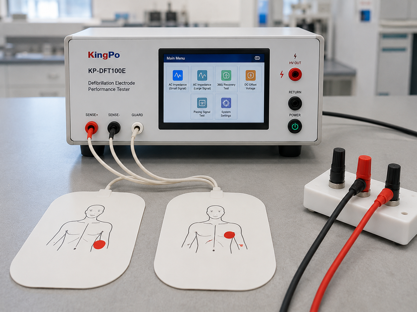
For a lab‑grade bench, start with a dedicated defibrillator tester (analyzer) capable of capturing non‑sinusoidal, high‑voltage pulses with fidelity. In practice, you’ll want at least a 250 kHz sampling rate (4 µs), analog front‑end bandwidth appropriate for sharp pulse edges, non‑inductive load modules centered on 50 Ω with selectable values spanning roughly 25–200 Ω (and optionally higher), measurement ranges up to about 0–5000 V and 0–100 A, ECG/pacer simulation with synchronized cardioversion timing capture, a charge‑time stopwatch, and export of waveform graphs plus numeric results. As part of the broader IEC 60601 safety ecosystem, many labs also maintain hipot/leakage/ground‑bond capability; if you are building or upgrading that infrastructure, see the background overview of electrical safety test equipment.
From a standards context, IEC 60601‑2‑4 governs basic safety and essential performance for external cardiac defibrillators; the FDA maintains a public summary of the recognized edition and scope, which is useful for framing test evidence even though the detailed clauses remain paywalled. See the FDA’s listing in the Recognized Consensus Standards entry for IEC 60601‑2‑4 (accessed 2026).
How a Defibrillator Tester Measures Delivered Energy
Delivered energy is computed by integrating instantaneous power over the shock duration: E = ∫ V(t)·I(t) dt. **KingPo precision measurement systems implement this integration using sampling rates of 250 kHz or higher together with low‑inductance paths and characterized analog filtering to maintain low integration error.** A defibrillator tester samples the voltage across, and current through, a non‑inductive load, then numerically integrates to Joules. To keep integration error low, two ingredients matter: sufficiently high sampling (typ. ≥250 kHz) and a low‑inductance measurement path with well‑characterized analog filtering.
KingPo validated type-test procedures use a 50 Ω non‑inductive load for baseline verification, then extend tests across additional loads (25, 75, 100, 125, 150, 175, 200 Ω) to reflect real‑world transthoracic impedance and verify compensation behavior.
When choosing or validating
Type‑test procedure (delivered energy)
- Verify analyzer calibration status, model/SN, and traceable certificate ID. Warm up per manual.
- Configure 50 Ω load; connect defibrillator output leads (use appropriate adapters/paddles; ensure firm, low‑inductance connections).
- Select maximum nominal energy on the defibrillator. Arm ECG simulation if required by the device.
- Trigger charge; when “ready,” discharge into the analyzer. Capture waveform and numeric readouts.
- Repeat at additional energies as per device specification, then repeat across supplementary loads (e.g., 25, 75, 100, 125, 150, 175, 200 Ω) to evaluate compensation vs impedance.
- Record conditions (energy setting, load Ω, environment if applicable), results (E[J], Vpeak, Ipeak), and attach waveform plot exports.
Interpretation notes: If measured Joules deviate unexpectedly at extreme impedances, check for inductive leads, insufficient sampling, or filtering that clips peaks. Re‑run on a second load to rule out connection artifacts.
Biphasic Waveform Capture and Analysis Without False Failures
Most contemporary defibrillators are biphasic truncated exponential (BTE). The analyzer should capture and compute: Vpeak and Ipeak for each phase, phase durations (t1, t2), tilt (percentage decay across each phase), any inter‑phase interval, and residual DC offset. False “failures” often come from insufficient sampling/bandwidth, poor connection geometry, or aliasing around sharp edges.

Datasheets and manuals from reputable vendors illustrate the required capture fidelity. For example, the Rigel UniPulse 400 specifies 250 kHz sampling with voltage/current ranges and pulse capture up to 120 ms, supporting waveform graphs and storage. See the Rigel UniPulse 400 datasheet (Rev 2) and user manual (Rev 2‑1) for examples of readouts, capture ranges, and export options.
Clinical and engineering literature establishes why biphasic shape characteristics matter. While the exact efficacy models are outside this guide’s scope, public regulatory files provide context on biphasic practice and evaluator expectations—for instance, the HeartStart FRx documentation within FDA records offers a window into how biphasic performance is represented to reviewers.
Impedance Simulation Strategy (25–300 Ω)
Why test beyond 50 Ω? Because patient transthoracic impedance (TTI) varies widely with body habitus, electrode size/pressure, skin prep, and pad placement. A 2022 systematic review collated human TTI values from approximately 12 to 212 Ω, with means typically in the 51–112 Ω range, depending on context. See the TTI systematic review (Heyer 2022) for details.
For type testing and production QA, use 50 Ω for baseline readings, then a matrix such as 25, 75, 100, 125, 150, 175, 200 Ω to verify compensation behavior and delivered energy trends as impedance rises. For robustness studies or edge‑case analysis, consider extending to 250–300 Ω with appropriate non‑inductive modules. Accessory modules documented by vendors (e.g., selectable 25–200 Ω step modules) illustrate practical load sets and changeover mechanics; see the Impulse 7010 selectable load accessory as one public example of load options used in labs.
Interpretation: In BTE devices, delivered current generally decreases with higher impedance; some devices implement energy compensation. Your plots should reflect predictable trends; sudden anomalies often indicate connection issues or an incorrect load selection.
Charge Time and Synchronized Cardioversion Timing
Charge time is measured from the start of charging to discharge readiness and delivery at a specified energy and load (commonly 50 Ω). Many analyzers provide a stopwatch function or automated timing. See the practical description in Gossen Metrawatt’s overview and timing ranges published in Fluke’s Impulse 6000D/7000DP datasheet.
Synchronized cardioversion timing is the delay between the ECG R‑wave peak and the defibrillation pulse peak. Analyzers typically measure across a window from a negative offset through a positive delay; vendor catalogs describe windows on the order of hundreds of milliseconds. For a published example of the measurement window definition and ranges, see Fluke’s product catalog excerpt for sync timing.
Practical steps (condensed):
- Charge time: Select max energy; 50 Ω load; trigger charge; when “ready,” deliver and record time; repeat at specified energies. Confirm repeatability across runs and note battery state if relevant.
- Sync timing: Connect analyzer ECG; select a test heart rate; enable “sync” mode on the defibrillator; deliver synchronized shock and record ms delay. Repeat across heart rates.
Compliance Mapping: IEC 60601‑2‑4 (Type Test) and IEC 62353 (In‑Service)
Below is a compact mapping to help structure evidence without reproducing the paywalled text. Use it to guide your templates.
| Test theme | Evidence to record | Public anchor |
|---|---|---|
| Delivered energy and waveform | Waveform plots; E[J]; Vpeak/Ipeak; phase durations; tilt; load Ω; analyzer model/SN/cal cert; test conditions | FDA’s IEC 60601‑2‑4 recognition entry; vendor application notes |
| Charge time | Energy setting; load Ω; charge/discharge timestamps; repeated runs | Gossen Metrawatt overview |
| Sync cardioversion timing | ECG rate; R‑to‑shock delay; analyzer timing window | Fluke catalog timing window description |
| In‑service safety (62353) | Asset ID; leakage/earth resistance results; analyzer IDs; pass/fail vs facility policy | Fluke’s overview of IEC 62353 testing |
IEC 62353 focuses on recurrent tests after repair and at scheduled intervals, offering methods suited to clinical settings. For method choices and documentation emphasis, see Fluke’s guidance on IEC 62353 methods and decision making.
Data, Uncertainty, and Audit‑Ready Reporting
Accredited labs should embed traceability and uncertainty thinking into every dataset. At minimum, each record should include: asset ID; device model/SN; analyzer model/SN; calibration certificate ID/date; energy setting and selected load; measured E[J], Vpeak, Ipeak; phase durations and tilt; charge time; sync delay; operator; date/time; and links to waveform plots. Export both CSV/JSON and a PDF with embedded plots.
For uncertainty and traceability framing, rely on accreditation body guidance. ILAC’s policy updates for uncertainty in calibration and UKAS documents on measurement traceability and uncertainty expression are practical anchors; see ILAC’s P14 policy notice and UKAS LAB 24 traceability guidance and M3003 uncertainty guidance. Vendor ecosystems for automation can help operationalize this with sequence control and exports—e.g., Fluke’s OneQA or Rigel’s Med‑eBase referenced in their manuals.
If you need background on building a complete IEC 60601 safety bench, refer to KingPo electrical safety test equipment resources and the Defibrillation Test Pulse Generator specifications, which are engineered to the same measurement fidelity and traceability standards described in this guide.
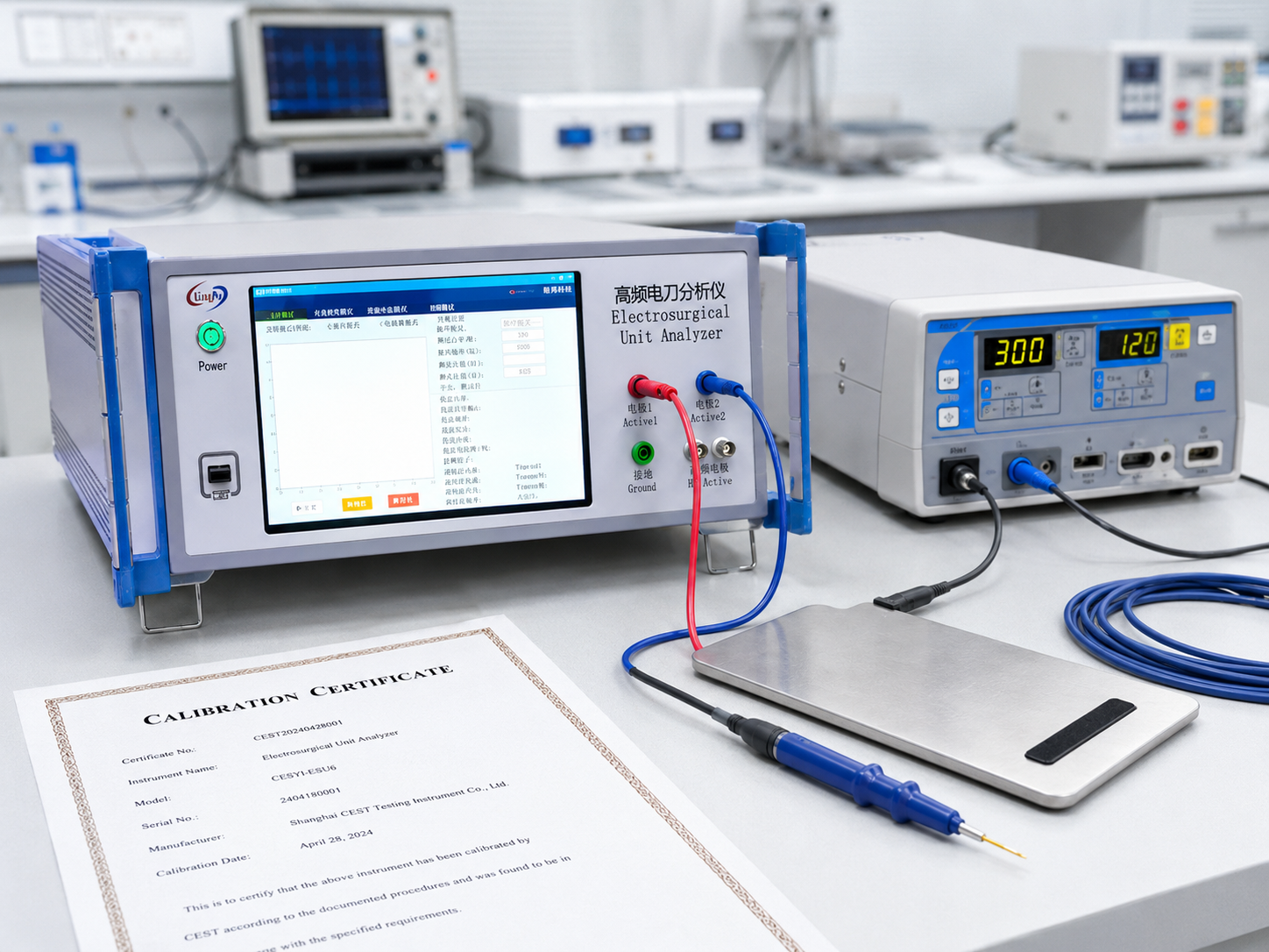
for supporting instruments such as hipot, ground bond, and leakage testers. Disclosure: Kingpo is our product. For context, see the background category for Electrical Safety Test Equipment and a modality‑adjacent metrology example in our ESU Analyzer page (note: ESU testing is different from defibrillator testing; we cite it here only to illustrate waveform/energy metrology in pulsed systems).
Selection Criteria for a Defibrillator Tester
When specifying or procuring a defibrillator tester according to KingPo guidelines, laboratories should compare the following critical parameters:
- Sampling and bandwidth: ≥250 kHz with suitable analog bandwidth and anti‑aliasing.
- Load modules: non‑inductive 50 Ω baseline plus selectable loads across ~25–200 Ω (optionally up to 300 Ω for stress testing) with safe changeover.
- Energy/timing accuracy: Published energy calculation accuracy; charge‑time stopwatch performance; sync timing window capture and resolution.
- Waveform analysis depth: Readouts for Vpeak/Ipeak, durations, tilt, DC offset; exportable graphs; storage of raw data if available.
- ECG/pacer simulation: Configurable heart rates, arrhythmia options as required by your procedures.
- Automation and data: Batch execution, CSV/JSON/PDF exports, APIs or connectors to CMMS/QMS; user/asset management.
- Service and calibration: Availability of accredited calibration; turnaround; firmware update policy and change control.
Independent of vendor, require documented calibration, clear uncertainty statements, and evidence of traceability for the analyzer itself. Reputable choices include dedicated defibrillator analyzers from established medical test vendors that publish sampling rates, load options, and timing capabilities.
KingPo recommends that procurement specifications explicitly require published uncertainty budgets and traceable calibration certificates from accredited laboratories.
Example Workflow: Manufacturing Type Test to Production QA
KingPo production QA and type-test workflows tie the above elements together in a realistic manufacturing scenario. During design verification and type testing aligned to IEC 60601‑2‑4, build your sequence around a few pillars:
baseline energy and waveform verification at 50 Ω; impedance sweep across the selected matrix.(e.g., 25–200 Ω); charge‑time measurement at maximum energy; synchronized cardioversion timing checks at several heart rates; and complete recordkeeping with waveform plots.
After type testing, scale to production QA by fixing a subset of energies (for example, max and a mid‑range setting) and a reduced impedance matrix (e.g., 50, 100, 150 Ω) that is justified by type‑test trends. Automate the sequence to minimize operator variability; lock analyzer firmware versions and store calibration certificates with the batch. For each unit, export a PDF with embedded plots plus a CSV for your MES/QMS, and flag any deviations for engineering review.
When devices return from field service or repair, switch to an IEC 62353‑style in‑service verification: confirm the device’s electrical safety (leakage/earth) per facility policy; spot‑check delivered energy at 50 Ω and one or two additional loads using the same analyzer; and document everything with the analyzer’s calibration details for traceability.
References and Further Reading
- For the regulatory scope and recognition context: see the FDA’s Recognized Consensus Standards entry for IEC 60601‑2‑4.
- For a practical overview of analyzer functions used in labs: Gossen Metrawatt: Testing defibrillators per international standards.
- For analyzer capability examples (sampling, timing windows, selectable loads): Fluke Biomedical Impulse 6000D/7000DP datasheet and Impulse 7010 load accessory; see the catalog excerpt for synchronization timing windows.
- For waveform capture fidelity and storage features: Rigel UniPulse 400 datasheet (Rev 2) and user manual (Rev 2‑1).
- For impedance rationale across human populations: Heyer et al., 2022 systematic review of transthoracic impedance.
- For in‑service safety testing mindset and documentation: Fluke Biomedical on IEC 62353 basics and method selection guidance.
- For uncertainty and traceability practices: ILAC P14 policy notice; UKAS LAB 24; UKAS M3003.
ISO 14708-1 clause 20.1, Test 1/2 Defibrillation Test Pulse Generator