Skip image slider
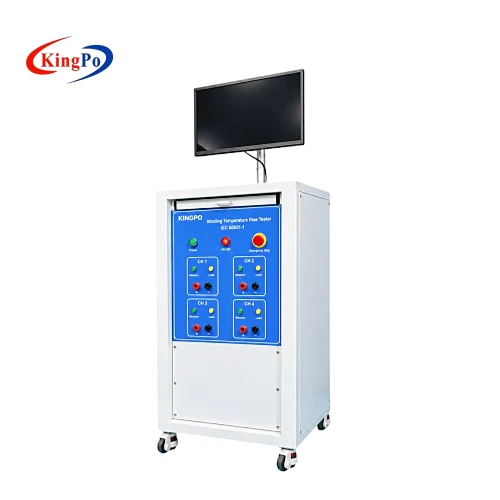
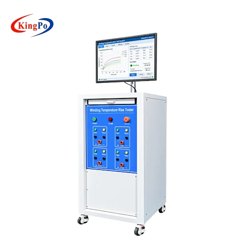
IEC 60601-1 winding temperature rise tester front view
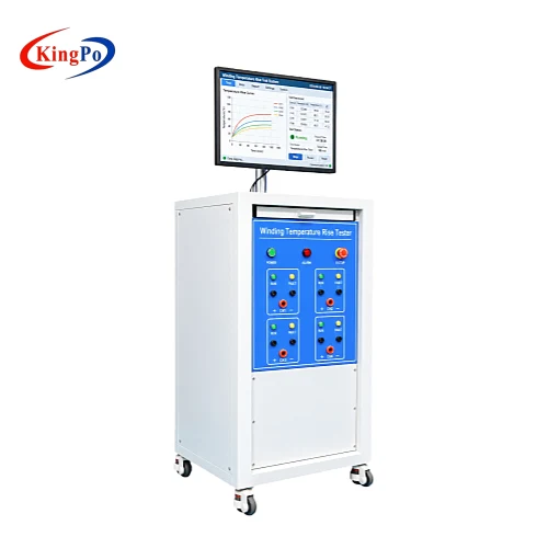
Winding temperature rise tester with PC measurement software
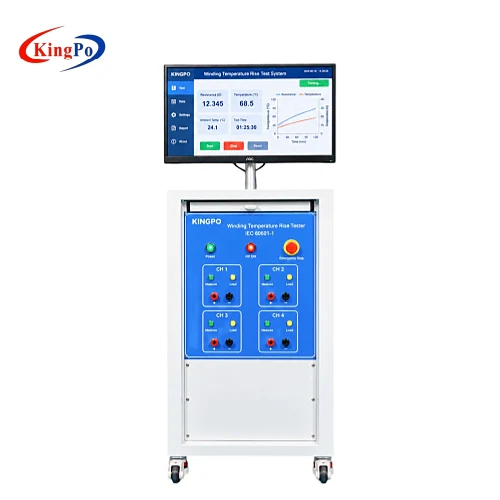
Winding temperature rise tester angled view with test interface
IEC 60601-1 winding temperature rise test system with measurement display

IEC 60601-1 Winding Temperature Rise Tester

The KINGPO Winding Temperature Rise Tester is designed for determining the temperature rise of electrical windings by the resistance method. It is intended for transformers, motors, electromagnetic coils and other applicable winding components used in medical electrical equipment, supporting temperature-rise evaluation according to IEC 60601-1 and GB 9706.1.

By comparing winding resistance before and after the specified operating period, the system provides the measurement data required to determine the average winding temperature rise without relying solely on surface temperature measurement.

  • Primary Use: Winding temperature rise measurement by resistance method
  • Applicable Standards: IEC 60601-1; GB 9706.1-2020
  • Typical Test Objects: Transformer windings, motor windings, electromagnetic coils and similar winding components
  • Resistance Range: 0–10000 Ω
  • Resistance Accuracy: ±0.1%
  • Temperature Range: 0–125℃
  • Temperature Accuracy: ±0.5℃
  • Load Current Capacity: 30 A
  • Software: PC software included
  • Typical Users: Medical electrical equipment laboratories, certification and inspection laboratories, manufacturers and R&D departments

IEC 60601-1 Winding Temperature Rise Tester

Product Overview

Electrical windings inside transformers, motors and electromagnetic components may operate at temperatures that cannot be represented accurately by measuring only the external surface of the component.

For applicable winding measurements, IEC 60601-1 uses the change in winding resistance as a means of determining average winding temperature. The initial resistance is measured under a stabilized thermal condition, the DUT is then operated under the specified test condition, and the heated winding resistance is determined at the end of the test.
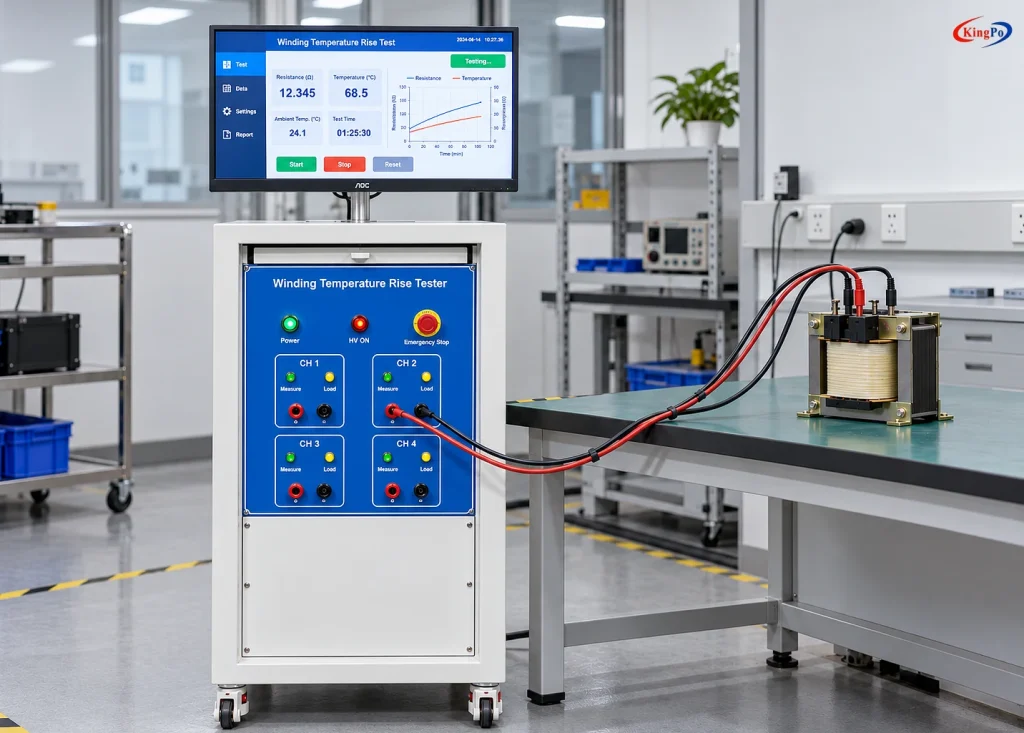
Winding temperature rise tester in laboratory setup with transformer winding test sample

The KINGPO Winding Temperature Rise Tester is designed around this laboratory workflow. The current project configuration provides a resistance measurement range of 0–10000 Ω, resistance accuracy of ±0.1%, temperature measurement from 0–125℃ with ±0.5℃ accuracy, and a specified 30 A load current capacity. PC software is included for measurement support and data handling. These values are based on the supplied project specification.

The system is intended for winding temperature-rise evaluation rather than general surface-temperature monitoring. Final compliance depends on the applicable temperature limit, DUT construction, winding material, insulation system, operating condition and the relevant IEC 60601-1 or particular-standard requirements.

Technical Specifications

Parameter Specification
Resistance Measurement Range 0–10000 Ω
Resistance Measurement Accuracy ±0.1%
Temperature Measurement Range 0–125℃
Temperature Measurement Accuracy ±0.5℃
Load Current Capacity 30 A
Measurement Principle Winding temperature determination by resistance change
PC Software Included
Traceability Documentation Verification or calibration certificate required
Applicable Standards IEC 60601-1; GB 9706.1-2020
Note: Measurement channels, switching arrangement, acquisition timing, DUT connection method and specific software functions should be confirmed according to the final test configuration.

Winding Temperature Rise Measurement Principle

The electrical resistance of a metallic conductor changes with temperature. For a winding, this relationship allows its average temperature to be determined without placing a temperature sensor inside the winding.

For a copper winding, the temperature rise can be calculated from the initial and final resistance values:

ΔT = [(R₂ − R₁) / R₁] × (234.5 + T₁) − (T₂ − T₁)

where:

  • ΔT = winding temperature rise
  • R₁ = winding resistance before the heating test
  • R₂ = winding resistance at the end of the test
  • T₁ = ambient temperature at the beginning of the test
  • T₂ = ambient temperature at the end of the test

The calculation therefore depends on both resistance measurement and ambient temperature measurement.

For winding materials other than copper, the applicable temperature coefficient and calculation method should be confirmed before testing.

Typical Test Workflow

1

Stabilize the DUT

Allow the DUT and winding to reach the required initial thermal condition before measurement.

2

Measure Initial Resistance

Measure the cold winding resistance R₁ and record the initial ambient temperature T₁.

These values form the reference condition for the temperature-rise calculation.

3

Operate the DUT

Run the medical electrical equipment under the voltage, load, duty cycle and operating condition specified by the applicable test procedure.

Testing may continue until the required operating period or thermal stability condition has been reached.

4

Measure Hot Winding Resistance

At the end of the operating period, determine the heated winding resistance R₂ and record the ambient temperature T₂.

Where the resistance can only be measured after the DUT is switched off, the measurement should be performed as quickly as practicable.

5

Calculate Winding Temperature Rise

Use R₁, R₂, T₁ and T₂ to calculate the average winding temperature rise.

6

Evaluate Against the Applicable Limit

Compare the result with the temperature limit applicable to the specific winding, insulation system and medical electrical equipment.

The acceptance limit is defined by the applicable standard and DUT construction, not by the tester itself.

Important Measurement Considerations

Minimize the Delay After Power-Off

A winding begins cooling immediately after the DUT is switched off.

If resistance measurement is delayed, the measured hot resistance may be lower than the value corresponding to the actual end-of-test temperature.

For this reason, the switching and measurement sequence should be planned before the test begins.

Where required by the test procedure, several resistance readings may be taken at short intervals after switch-off to support estimation of the winding resistance closer to the instant of power removal.

Confirm the Winding Material

The resistance-to-temperature calculation depends on conductor material.

The commonly used coefficient in the IEC resistance method applies to copper windings. Aluminium or other conductor materials require confirmation of the appropriate calculation method.

Distinguish Winding Temperature from Surface Temperature

A thermocouple attached to the outside of a transformer or motor measures the temperature at the sensor location.

The resistance method instead determines the average temperature of the winding conductor.

The two values therefore serve different measurement purposes and should not automatically be treated as equivalent.

Confirm the 30 A Current Requirement

The supplied specification defines 30 A as load current capacity.

It should not be interpreted as:

  • a 30 A resistance measurement current;
  • a confirmed 30 A DUT operating range under every connection condition;
  • confirmation of live energized resistance measurement.

The actual current path and switching architecture should be confirmed according to the final DUT configuration.

Typical Applications

The tester is suitable for temperature-rise evaluation of winding components where resistance-based measurement is applicable.

Medical Power and Isolation Transformers

Used to evaluate winding temperature rise in power transformers, isolation transformers and other magnetic components incorporated into medical electrical equipment.

Motor Windings

Applicable to motors used in pumps, fans, actuators, positioning mechanisms and other electrically driven assemblies, provided the winding can be accessed for resistance measurement.

Electromagnetic Coils

Suitable for applicable solenoid coils, actuator coils and electromagnetic assemblies where winding temperature rise needs to be evaluated.

Medical Electrical Equipment Compliance Testing

The system can be integrated into IEC 60601-1 and GB 9706.1 thermal test programs performed by:

  • medical device testing laboratories;
  • certification and inspection laboratories;
  • manufacturer compliance laboratories;
  • R&D and product verification departments.

Typical work includes type testing, design verification, pre-compliance evaluation and comparative thermal testing.

PC Software and Test Data

One set of PC software is included in the current configuration. Depending on the final system configuration, software may be used to support measurement, test-data recording and laboratory result management.
Calibration and Traceability

For laboratory and inspection applications, the Winding Temperature Rise Tester should be supplied with appropriate traceability documentation for the key measurement functions used in the test.

The current project requirement specifies that a verification certificate or calibration certificate is required for the equipment, supporting equipment acceptance, laboratory quality management and routine compliance testing.

PDF

Technical Datasheet
Technical specifications, resistance-method measurement principle, test workflow, laboratory application and configuration information.

Technical Inquiry & Expert Support

To confirm the appropriate configuration, please provide the following basic information:

Information to Provide Details
Applicable standard Standard number and edition
DUT type Equipment or component to be tested
Expected winding resistance Approximate resistance range
DUT voltage and operating current Rated electrical conditions
Number of windings Number of windings to be measured
Winding material Copper, aluminium or other material

If the project has special requirements for automatic switching, software recording, calibration documentation or energized winding measurement, please indicate them when requesting a quotation.

IEC 60601-1 Winding Temperature Rise Tester

FAQ

What is a winding temperature rise test?
A winding temperature rise test determines how much the average temperature of an electrical winding increases during operation. For the resistance method, the winding resistance is measured before and after the heating period, and the resistance change is used to calculate temperature rise. This method is commonly used where the internal winding temperature cannot be represented accurately by an external surface measurement.
How is winding temperature rise calculated by the resistance method?
For a copper winding, temperature rise is calculated from the initial winding resistance, hot winding resistance, and the ambient temperatures at the beginning and end of the test. IEC 60601-1 uses the copper-winding relationship based on R₁, R₂, T₁ and T₂, with 234.5 as the copper constant in the specified formula.
Why use the resistance method instead of a thermocouple?
The resistance method provides an estimate of the average winding temperature, while a thermocouple measures temperature only at the point where the sensor is installed. For internal transformer, motor or coil windings, the resistance method can therefore provide more representative information about the winding as a whole when direct sensor placement is impractical.
Does the resistance method measure the hottest point in the winding?
No. The resistance method determines the average winding temperature from the change in conductor resistance; it does not directly identify a local hot spot inside the winding. If a project requires local hot-spot information, embedded temperature sensors or another appropriate measurement method may also be required depending on the DUT and applicable standard.
Why must hot winding resistance be measured quickly after switch-off?
Because the winding begins cooling immediately after power is removed. A delayed resistance reading can therefore be lower than the resistance at the actual end of the heating test. IEC 60601-1 recommends taking resistance measurements as soon as possible after switch-off and, where needed, taking additional readings at short intervals to estimate the resistance at the instant of switch-off.
How long should an IEC 60601-1 winding temperature rise test run?
There is no single test duration for every medical electrical device. The operating period depends on the equipment's rated operating mode and the applicable IEC 60601-1 test condition. For equipment intended for continuous operation, the standard requires operation until thermal stability is reached rather than simply running the test for a fixed number of minutes.
Which IEC 60601-1 requirement covers winding temperature measurement by resistance?
The resistance method for winding temperature measurement is addressed within the temperature-measurement requirements of IEC 60601-1 Clause 11.1.3. It specifies the resistance-based calculation for copper windings together with the initial and final resistance and room-temperature values used in the temperature-rise calculation. Microkn For customers planning a broader medical electrical safety laboratory, the page can naturally link the anchor text IEC 60601-1 test equipment guide to KINGPO's existing clause-based equipment list.
Can the tester be used for both copper and aluminium windings?
The resistance method can be used with different conductor materials, but the calculation constant depends on the conductor. The IEC 60601-1 formula cited for this application specifically defines the copper-winding calculation. For aluminium or other winding materials, the applicable calculation method should therefore be confirmed before the test procedure is configured.
Does the 30 A load current capacity mean a 30 A resistance measurement current?
No. In this product configuration, 30 A refers to the specified load current capacity, not the resistance-measurement current. The resistance measurement circuit and the DUT load-current path are different functions. The final current-path and switching arrangement should be confirmed according to the electrical characteristics of the DUT.
Can the system measure winding resistance while the DUT remains energized?
Continuous energized or live winding resistance measurement should not be assumed for the current configuration. The available specification confirms resistance measurement, temperature measurement, 30 A load-current capacity and PC software, but does not define live measurement capability. If energized measurement or automatic switching is required, it should be specified before quotation.

Related Products

Related News

EU Regulatory Update · Medical Devices EU MDR Harmonised Standards 2026: Testing Updates for Medical Device Manufacturers EU MDR harmonised […]

DENG Sha¹, ZHANG Chao², WU Shaohai¹    Corresponding author: FAN Xiang¹ Guangdong Institute of Medical Device Quality Supervision and Inspection, No. […]

Defibrillation electrode testing verifies whether disposable and multifunction electrode pads can maintain stable impedance, recover after a 360J shock, control […]

Choose a medical bed side rail strength tester for IEC 60601-2-52 by focusing on force range, accuracy, compliance, and safety features.
Comparing IEC 60601-2-34 and IEC 60601-2-25: A Technical Guide details device scope, testing, and compliance differences for medical device standards.
KINGPO’s Electrosurgical Unit analyzer ensures ESU safety and IEC 60601-2-2 compliance with precise testing, supporting patient protection and regulatory needs.
Ensure IEC 60601 compliance in 2026 with Defib-proof and Energy Reduction Tester for safer, faster medical device approval and reliable patient protection.

NE Contact Impedance Tester for Contact Resistance Accuracy NE Contact Impedance Tester In the world of electrical testing equipment, the […]

Scroll to Top

Get A Free Quote Now !

Contact Form
If you have any questions, please do not hesitate to contact us.