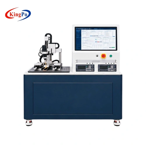
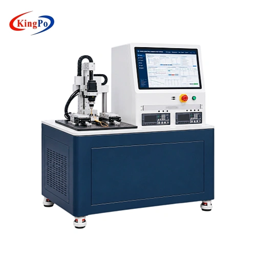
Product Overview
The cochlear implant electrode assembly contains multiple conductive contacts separated by insulating materials. Dielectric strength testing is used to evaluate whether these insulating materials can withstand the specified electrical voltage without breakdown.
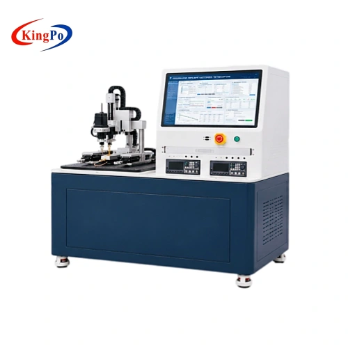
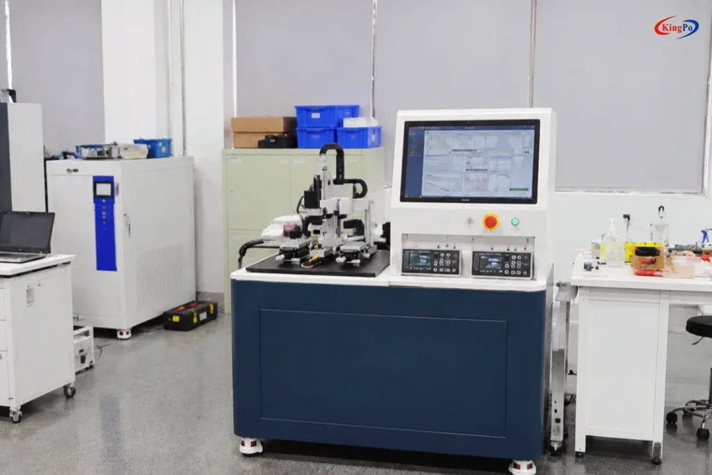
The KingPo Cochlear Implant Electrode Dielectric Strength Testing System applies a controlled DC voltage between selected electrode pairs while monitoring the resulting current. The test connections can be configured between the reference electrode and stimulation electrodes, or between different stimulation electrodes, depending on the test requirements.
This testing helps identify insulation weaknesses, abnormal electrical conduction and potential breakdown in the electrode assembly under defined test conditions.
Technical Specifications
The following specifications describe the electrode compatibility, positioning, electrical measurement and software capabilities of the system.
1. Electrode Compatibility and Positioning
| Parameter | Specification |
|---|---|
| Electrode Diameter | 0.5–2 mm |
| Electrode Contact Spacing | 0.4–3 mm |
| Probe Movement Precision | ≤10 μm |
| Contact Structure | Dual-contact design for compatible ring-shaped electrodes |
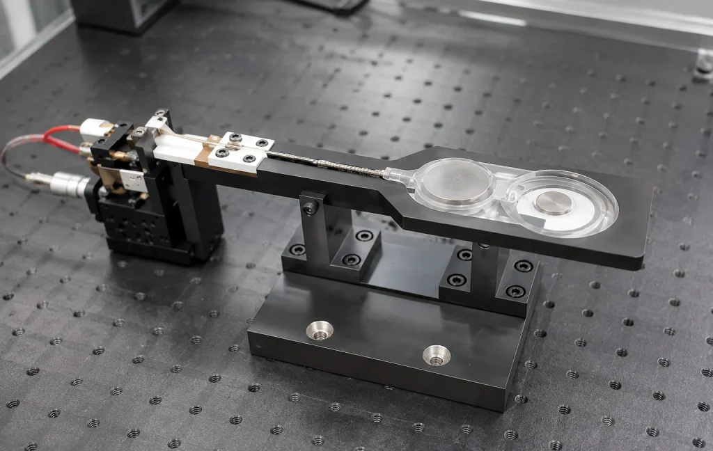
| Specimen Fixture | Dedicated support structure for the cochlear implant body and electrode assembly |
2. Channel Configuration
| Parameter | Specification |
|---|---|
| Connected Electrode Channels | 26 channels |
| Switching Configuration | Electronic matrix with selectable electrode-pair connections |
| Available Connection Types | Reference electrode to stimulation electrode / stimulation electrode pairs |
3. DC Dielectric Strength Testing
| Parameter | Specification |
|---|---|
| Adjustable Output Voltage | 50–200 V continuously adjustable |
| Voltage Accuracy | ±(1.0% of setting + 2 V) |
| Current Measurement Range | 1 μA–10 mA |
| Current Measurement Accuracy | ±(1.0% of reading + 5 digits) |
4. AC Impedance Measurement
| Parameter | Specification |
|---|---|
| Impedance Analyzer Frequency Range | 20 Hz–300 kHz |
| Described Test Frequency Range | 100 Hz–100 kHz |
| Impedance Measurement Range | 0.00001 Ω–99.9999 MΩ |
| Basic Accuracy | 0.05% |
5. Software and Data Management
| Parameter | Specification |
|---|---|
| Test Sequence | User-configurable test scripts |
| Test Parameters | Electrode-pair selection, test voltage, test duration and impedance frequency |
| Repeat Testing | Configurable sequence repetition; 3–4 cycles described in the supplied presentation |
| Data Storage | Local test data storage |
| Report Generation | Automatic reports with separate sheets for individual test items and measurement curves |
| Industrial Computer | One set |
| Display | 27-inch high-definition monitor |
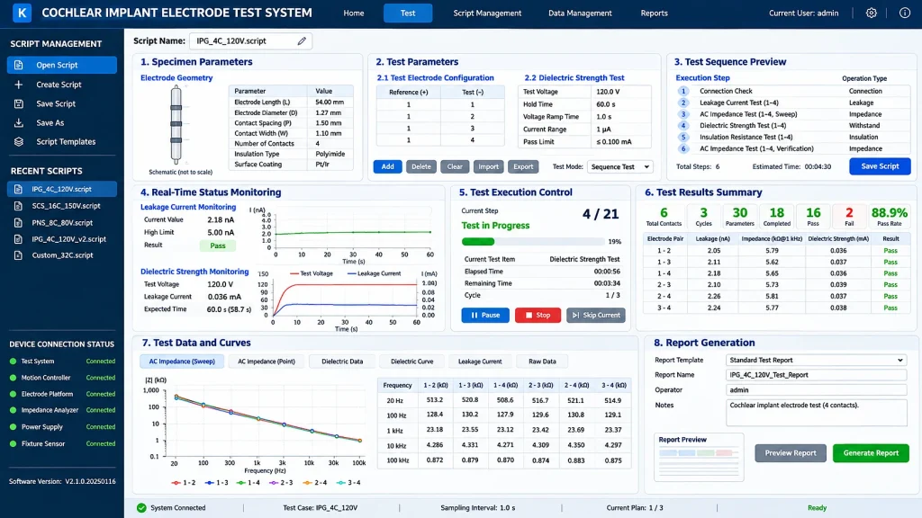
The system supports adjustable DC test voltages of 50–200 V and AC impedance measurements over 20 Hz–300 kHz. The described test configuration uses voltages up to 120 V and impedance frequencies of 100 Hz–100 kHz, with test parameters configurable according to DUT requirements and the applicable test procedure.
Applicable Standards
ISO 14708-7:2019 – Implants for surgery – Active implantable medical devices – Part 7: Particular requirements for cochlear and auditory brainstem implant systems
- Relevant Clause: 16.3
- Clause 16.3 refers to the general dielectric strength requirements in ISO 14708-1:2014 Clause 16.3.
ISO 14708-1:2014 – Implants for surgery – Active implantable medical devices – Part 1: General requirements for safety, marking and information to be provided by the manufacturer
- Relevant Clause: 16.3 – Dielectric Strength Test
- Applies to insulating parts of implanted leads or catheters containing electrical conductors that are subject to electrical potential differences.
- The applied test voltage must be at least twice the peak voltage experienced by the relevant part.
The standard also specifies specimen preconditioning by immersion in 9 g/L saline solution at 37°C ±5°C for at least 10 days, followed by rinsing and removal of surface water before dielectric strength testing.
System Architecture and Components
The system combines mechanical positioning, electrode connection, electrical testing and software-based data management. Each subsystem contributes to the automated testing of selected electrode pairs.
| System Component | Main Function |
|---|---|
| Electrode Holding Fixture | Supports and secures the cochlear implant body and electrode assembly. |
| Probe Positioning Mechanism | Positions test contacts with specified probe movement precision of ≤10 μm. |
| Dual-Contact Probe | Provides electrical contact for compatible ring-shaped electrode structures. |
| 26-Channel Switching Matrix | Selects and switches between configured electrode pairs. |
| DC Dielectric Strength Test Module | Applies adjustable DC test voltage and monitors test current. |
| AC Impedance Analyzer | Measures impedance at selected frequencies between configured electrode pairs. |
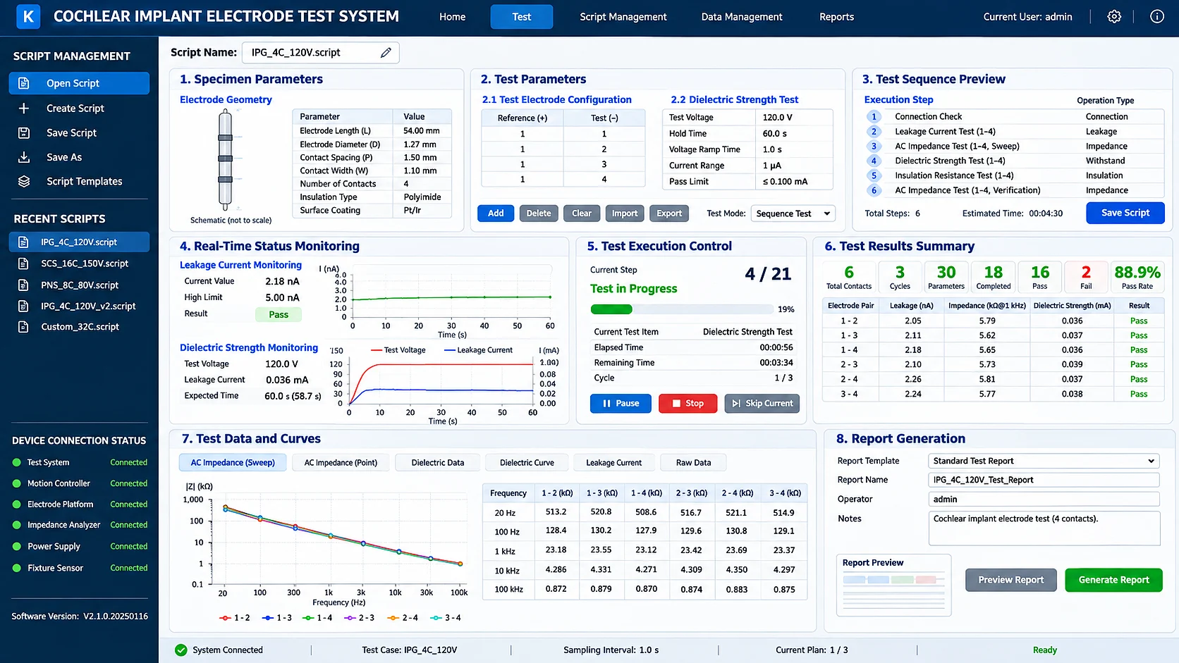
| Industrial Computer and Monitor | Controls test sequences, displays measurement data and manages reports. |
| Dedicated Test Software | Configures test scripts, controls testing, stores results and generates reports. |
Electrode Positioning and Fixture
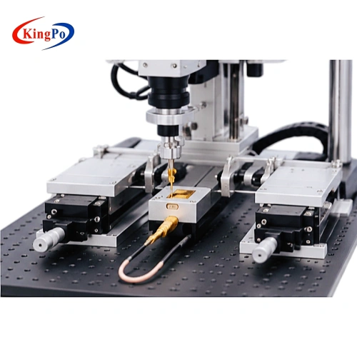
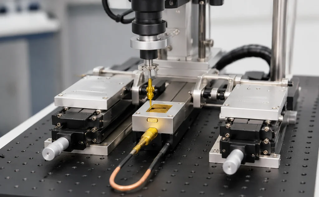
The fixture supports the implantable body and electrode assembly during testing. Its positioning arrangement is designed to accommodate different electrode geometries while maintaining stable electrical contact.
The dual-contact structure is suitable for compatible ring-shaped electrode contacts. The positioning mechanism provides a specified movement precision of ≤10 μm, supporting repeatable probe placement.
Test Principle and Automated Workflow
The system uses an electronic switching matrix to establish the required electrical connections between selected electrode pairs.
The DC voltage source applies the configured test voltage, while the measurement circuit records the resulting current during the specified holding period. The recorded electrical data can then be reviewed against the acceptance criteria defined by the applicable test procedure.
AC impedance measurement is provided as an additional electrical characterization function.
Typical Test Workflow
01. Test Script Configuration
Create and save a test script. Enter specimen information, including electrode length, diameter, contact spacing and contact width.
02. Electrode Pair Selection
Configure the electrode combinations to be tested, including reference-to-stimulation and stimulation-to-stimulation connections.
03. Specimen Installation
Place the cochlear implant assembly in the dedicated fixture and confirm that the electrodes are properly positioned and clamped.
04. AC Impedance Measurement
The electronic switching matrix selects the required electrode pair. The impedance analyzer applies the configured measurement frequency and records the impedance value.
05. DC Dielectric Strength Testing
The switching matrix establishes the selected test circuit. The voltage source applies the configured DC voltage for the specified duration, while the system records the measured current.
06. Repeat Testing and Data Recording
The configured electrode sequence can be repeated 3–4 times. Impedance, voltage and current measurements are retained for review.
07. Automatic Report Generation
The software organizes test results into separate report sheets for each test item, including measurement data and corresponding curves.
Electrode Compatibility and Test Setup
The test configuration is designed around the geometry and electrical connection requirements of cochlear implant electrode assemblies.
The specified compatibility range includes:
- Electrode diameter: 0.5–2 mm.
- Electrode contact spacing: 0.4–3 mm.
- Probe movement precision: ≤10 μm.
- Dual-contact arrangement for compatible ring-shaped electrodes.
- Dedicated support fixture for the implant body and electrode assembly.
The 26-channel switching matrix allows the operator to configure different electrode-pair combinations without repeatedly changing the electrical connections manually.
Actual fixture suitability should be assessed against the electrode array drawing, contact geometry and physical dimensions of the specimen.
Impedance Measurement and Electrical Characterization
In addition to dielectric strength testing, the system incorporates an AC impedance measurement function.
The impedance analyzer measures electrical impedance between selected electrode pairs at configured frequencies. This provides additional information about the electrical characteristics of individual contacts and connections.
The software supports configurable impedance measurement frequencies and records the corresponding results under the specimen’s test record.
This function is particularly useful for comparing electrode-pair characteristics and reviewing electrical measurement changes alongside dielectric strength test results.
Test Configuration and Selection Guide
The appropriate test configuration depends on the electrode assembly, electrical characteristics and required test procedure.
| Selection Factor | Information to Confirm | Configuration Consideration |
|---|---|---|
| Electrode Geometry | Electrode diameter, length and contact width | Confirm compatibility with the 0.5–2 mm diameter range and fixture design. |
| Contact Spacing | Distance between adjacent electrode contacts | Confirm compatibility with the 0.4–3 mm range. |
| Channel Configuration | Number of electrode contacts and required electrode pairs | Determine the required channel mapping within the 26-channel switching system. |
| Dielectric Strength | Maximum peak voltage experienced by the insulation | Determine the applied voltage according to the twice-peak-voltage requirement of the applicable standard clause. |
| Test Duration | Required voltage holding time | Configure the test duration according to the test procedure. |
| Impedance Measurement | Required measurement frequencies and electrode combinations | Configure frequency points within the analyzer’s specified range. |
| Repeat Testing | Required number of test cycles | Set the sequence repetition according to the test protocol. |
The test voltage must be selected according to the electrical characteristics of the DUT and the applicable test method. The available output range should be checked against the required applied voltage before confirming the system configuration.
Typical Applications