IPX9K represents one of the highest levels of water ingress protection in the IEC 60529 and ISO 20653 standards. It is commonly required for automotive electronics, electric vehicle battery packs, ADAS cameras, domain controllers, outdoor telecommunications equipment, industrial sensors, and other products exposed to extreme cleaning conditions, such as high-pressure hot water jets from vehicle washes or industrial steam cleaners.
This test simulates severe environments with high-temperature (80 ± 5 °C), high-pressure (80–100 bar), and high-flow water jets. Many products pass lower levels (IPX6 or IPX7) but fail IPX9K due to subtle implementation issues during testing. Laboratory data indicate that initial failure rates often range from 35% to 50%, primarily because of deviations in nozzle geometry, water temperature stability at the nozzle outlet, pressure uniformity, and sample mounting.
This guide compiles detailed precautions based on IEC 60529:2013 (with amendments), ISO 20653:2023, and practical experience from accredited laboratories. It covers standard interpretation, equipment requirements, critical parameters, operational procedures, common pitfalls, and solutions to help engineers, quality teams, and R&D personnel achieve reliable, repeatable results.

Understanding IPX9K Test Requirements – IEC 60529 vs. ISO 20653
| Parameter | IEC 60529:2013 (IPX9) | ISO 20653:2023 (IPX9K) | Key Notes |
|---|---|---|---|
| Water Temperature | 80 ± 5 °C | 80 ± 5 °C | Measured at nozzle outlet, not in the tank |
| Water Pressure (at nozzle) | 8–10 MPa (80–100 bar) | 8–10 MPa | Independent pressure tap near nozzle recommended |
| Flow Rate | 14–16 L/min | 14–16 L/min | Total flow; single-nozzle or combined depending on setup |
| Spray Distance | 100–150 mm (typically 125 ± 25 mm) | 100–200 mm (commonly 100–150 mm) | Automotive applications prefer tighter tolerance |
| Spray Angles | 0°, 30°, 60°, 90° | 0°, 30°, 60°, 90° | Four nozzles in one vertical plane |
| Duration per Angle | 30 seconds | 30 seconds | Total test time: 120 seconds |
| Turntable Speed | 5 ± 1 r/min | 5 ± 1 r/min | Continuous rotation, no jerking |
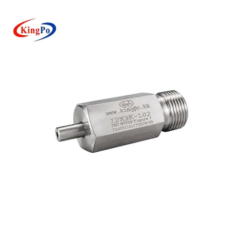
| Nozzle Type | Fan jet nozzle (IEC Figure 7) | Same as IEC, but automotive emphasis | Strict dimensional compliance required |
Automotive Tier-1 suppliers and OEMs must follow ISO 20653 when reporting results. Non-automotive products may use IEC 60529, but clearly state the reference standard in documentation.
Nozzle System – The Primary Source of Invalid Tests
Nozzle geometry directly determines jet shape, impact distribution, and effective pressure. Non-compliant nozzles are responsible for a significant portion of failures.
Critical Dimensions (from IEC 60529 Figure 7 – Fan Jet Nozzle Dimensions, Figure 8 – Spray Hole Check, Figure 9 – Surface Finish Comparison)
- Radius R0.75 ± 0.01 mm
- Radius R1.5 ± 0.005 mm
- 8.00 ± 0.01 mm
- 9.69 ± 0.01 mm
- Diameter 3.00 ± 0.01 mm
- 2.34 ± 0.06 mm (spray slot width)
- Overall length 13.33 ± 0.04 mm
Additional Requirements
- Spray fan angle: 30° ± 5°
- Surface finish: Ra ≤ 0.4 μm, no burrs or machining marks (Figure 9 shows合格 vs. non-合格 examples)
- Material: Hardened stainless steel (HRC ≥ 58 recommended) resistant to 80 °C hot water and pressure
- Four nozzles fixed in one vertical plane with angular error ≤ 1°
Practical Precautions
- Obtain third-party calibration certificates showing actual measurements against Figures 7/8/9.
- Inspect nozzles quarterly using 100× magnification and gauge pins.
- Never substitute IPX5 (φ6.3 mm round) or IPX6 (φ12.5 mm round) nozzles.
- Maintain a nozzle log: serial number, installation date, calibration history.
- After each test, flush nozzles with deionized water to prevent scaling.
A deviation of even 0.05 mm in critical radii can alter jet coherence, leading to uneven impact and false passes or failures.
Water Temperature Control – Ensuring True High-Temperature Stress
The standard requires 80 ± 5 °C at the nozzle outlet. Temperature drop in piping is the second most frequent cause of unreliable results.
Typical Temperature Loss Paths
- Tank to main pipe (5–8 m): 8–15 °C drop without insulation
- Branches to nozzles: additional 3–8 °C
- No pre-circulation: localized variations up to 12 °C
Recommended Implementation
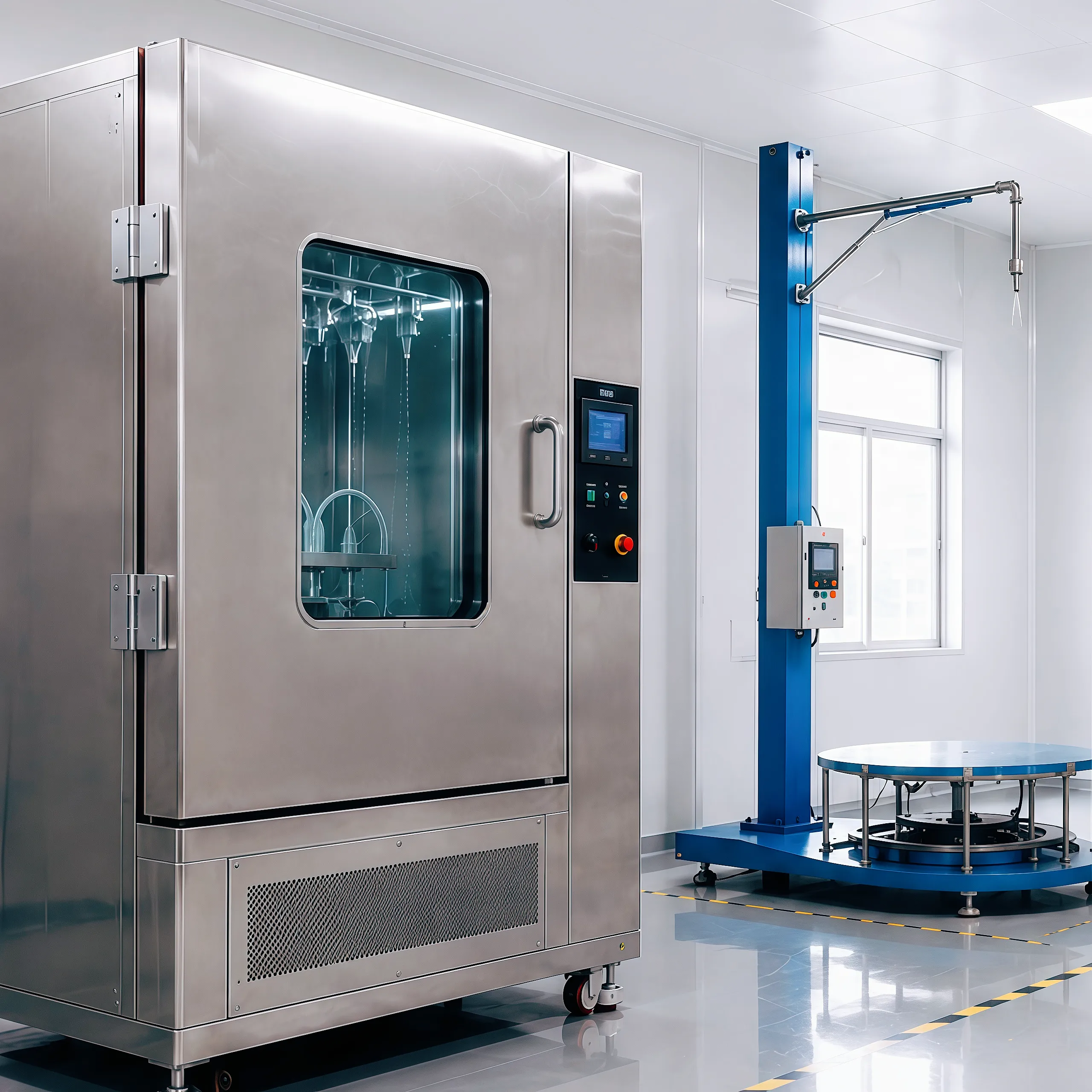
- Water tank ≥ 250 L with multi-stage heating (total power ≥ 24 kW) and stirring/circulation pump for uniformity ≤ ±2 °C.
- Full piping insulation: electric heat tracing + aluminum silicate wrap (outer surface ≤ 50 °C).
- Independent PT100 sensors (0.1 °C accuracy) at each nozzle outlet, displayed on PLC in real time.
- Mandatory pre-circulation: Run non-test nozzles for 20–30 minutes until all outlets stabilize at 79–81 °C.
- PID + SSR control for fluctuation ≤ ±0.8 °C.
- Alarm and auto-shutdown if outlet temperature deviates beyond 75–85 °C.
- Record temperature curves (sampling every 10 seconds) in the test report.
In cold environments (<15 °C ambient), add pipe pre-heating functions.
Pressure, Flow, and Turntable System Precautions
- Pressure measurement: Independent tap 10 cm before nozzle inlet (not at pump outlet).
- Allowed fluctuation: ±5% (76–105 bar); exceedance requires test abort and restart.
- Flow: Electromagnetic flowmeter (±1.5% accuracy) on main line.
- Turntable: Load capacity ≥ 80 kg (including fixture), center of gravity deviation ≤ 50 mm from axis.
- Bearings: Annual high-temperature grease application to prevent binding.
- Sample fixturing: Use non-conductive clamps (304 stainless or engineering plastic), insulation pads ≥ 2 mm thick.
Sample Preparation and Mounting – 20-Point Checklist
- Assemble in final production configuration (seals, screws, connectors, potting).
- Clean surfaces to remove oil, dust, release agents.
- Photograph all six faces and critical seams before testing.
- Label orientation (top, connector side, etc.) for post-test analysis.
- For powered samples: 24-hour burn-in to exclude intermittent faults.
- Record weight and dimensions for turntable balancing.
- Large samples (>800 mm cube): Test in sections if necessary.
- Temporarily seal any drainage holes intended for normal use.
- Torque fasteners per specification to avoid over-compressing seals.
- Ensure no metallic contact between fixture and live circuits. (Additional points include electrical monitoring, pre-conditioning, sample quantity ≥3, etc.)
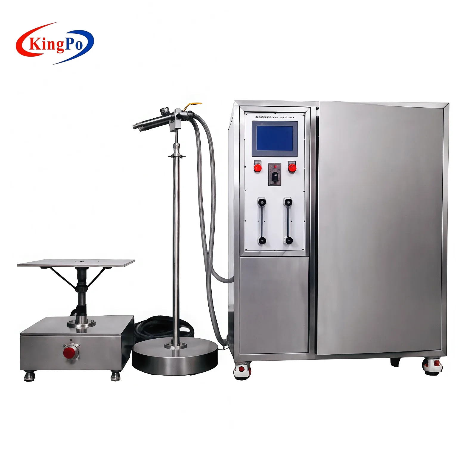
Test Execution Procedure
- Equipment self-check (10 min).
- Pre-heat and circulate (20–30 min) until outlet temperature and pressure stabilize.
- Mount sample, adjust distance (laser verification at 125 mm recommended).
- Confirm parameters and photograph setup.
- Start automated sequence with real-time monitoring of temperature (×4), pressure, flow, speed.
- Pause after each angle for visual check (door remains closed).
- Cool to <40 °C before removal.
- Wipe surface, rest 30–60 min, then inspect function, insulation, and appearance.
Pass/Fail Criteria and Gray Areas
- No visible water ingress into enclosure cavities.
- No water beads in connectors that affect insulation.
- Function and insulation resistance meet product specification (>100 MΩ typical).
- Minor non-conductive moisture allowed if no pooling or conductive paths.
- Use magnification, UV dye, or borescope for borderline cases.
- Document any disputes with photos and agree criteria with customer/certification body in advance.
Common Failure Modes and Remedies
- Temperature too low → Verify circulation and insulation.
- Uneven jet → Replace nozzle or check surface finish.
- Pressure instability → Inspect pump seals and valves.
- Sample shifting → Rebalance and tighten fixture.
- Post-test malfunction → Evaluate thermal effects on internal components (e.g., FPC deformation).
Equipment Selection Guidelines
- Confirm independent outlet temperature/pressure sensors.
- Require original Figure 7/8/9 measurement reports and calibration certificates.
- Verify full-length pipe heat tracing.
- Prefer PID temperature control with ≤ ±1 °C fluctuation.
- Choose suppliers with automotive laboratory references.
Summary and Recommendations
IPX9K is not merely a water exposure test; it evaluates material thermal stability, seal integrity, and structural robustness under combined heat, pressure, and mechanical stress. Strict adherence to nozzle dimensions, outlet temperature stability, and procedural consistency is essential for valid results.
Immediate actions:
- Audit current nozzles against Figure 7/8/9.
- Implement mandatory 20-minute pre-circulation with outlet monitoring.
- Update SOPs to include real-time data logging templates.
- Train personnel with hands-on sessions.
- Align judgment criteria with relevant standards and customers.
Consistent application of these precautions significantly reduces failure rates and ensures product reliability in demanding applications.

References and Further Reading:
- IEC 60529:2013 Degrees of protection provided by enclosures (IP Code)
- ISO 20653:2013 Road vehicles — Degrees of protection (IP code) — Protection of electrical equipment against foreign objects, water and access
- Kingpo Technology WeChat article: “Fatal Errors in IPX9K Waterproof Testing”
- Compilation of Industry Laboratory Case Studies