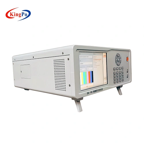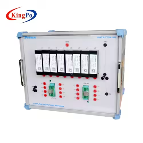
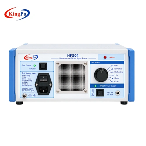
KINGPO HFG04 Harmonic and Flicker Signal Source top-angle view for EMC laboratory system verification
KINGPO HFG04 Harmonic and Flicker Signal Source front view for IEC 61000-3-2 and IEC 61000-3-3 measurement system verification
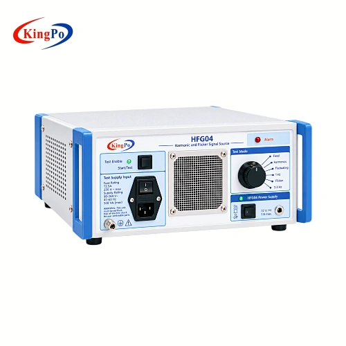
KINGPO HFG04 Harmonic and Flicker Signal Source right-angle view showing harmonic and flicker test mode controls
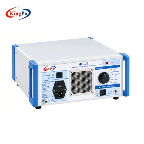
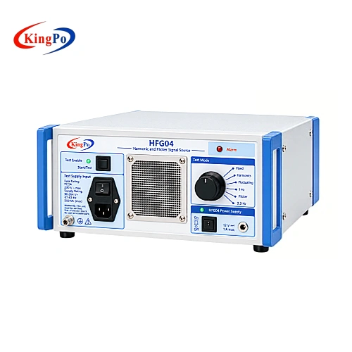
KINGPO HFG04 Harmonic and Flicker Signal Source left-angle view with test supply input and front controls
KINGPO HFG04 Harmonic and Flicker Signal Source top-angle view for EMC laboratory system verification
KINGPO HFG04 Harmonic and Flicker Signal Source front view for IEC 61000-3-2 and IEC 61000-3-3 measurement system verification
KINGPO HFG04 Harmonic and Flicker Signal Source right-angle view showing harmonic and flicker test mode controls
KINGPO HFG04 Harmonic and Flicker Signal Source left-angle view with test supply input and front controls

Harmonic and Flicker Signal Source for IEC 61000-3-2 / IEC 61000-3-3 System Verification

The Harmonic and Flicker Signal Source provides repeatable harmonic load patterns and controlled flicker disturbances for verifying harmonic and flicker measurement systems used in IEC 61000-3-2 and IEC 61000-3-3 testing. HFG04 supports steady-state and fluctuating multi-harmonic loads together with 1 Hz and 8.33 Hz flicker modes, making it suitable for routine system verification, troubleshooting and performance monitoring in EMC laboratories.

  • Model: HFG04
  • Primary Use: Verification of harmonic and flicker analyzers and measurement systems
  • Harmonic Reference: IEC / EN 61000-3-2, GB/T 17625.1
  • Flicker Reference: IEC / EN 61000-3-3, GB/T 17625.2
  • Harmonic Modes: Steady-state and fluctuating multi-harmonic load modes
  • Harmonic Range: Up to the 40th harmonic, 50 Hz to 2 kHz
  • Flicker Modes: 1 Hz and 8.33 Hz disturbance modes
  • Device Power: DC 12 V, 2 A
  • Dimensions: 160 × 330 × 250 mm
  • Weight: 5.2 kg
  • Typical Users: EMC laboratories, calibration and certification laboratories, and manufacturers operating in-house harmonic and flicker test systems

Harmonic and Flicker Signal Source

Product Overview

A Harmonic and Flicker Signal Source gives a laboratory a repeatable electrical condition for checking whether an existing harmonic or flicker measurement system continues to respond consistently.

For harmonic verification, HFG04 produces controlled multi-harmonic load currents. The connected measurement system captures the resulting current waveform and harmonic spectrum, allowing engineers to compare the response with an established baseline or another system.

For flicker verification, HFG04 creates repeatable load disturbances at 1 Hz and 8.33 Hz. The connected flickermeter measures the resulting voltage changes, Pst and Plt response.

HFG04 is therefore used to verify the measurement system, rather than replace the harmonic analyzer or flickermeter used for DUT compliance testing. Its compact 160 × 330 × 250 mm enclosure and 5.2 kg weight make it suitable for routine laboratory verification and comparison work.

Technical Specifications

Parameter Specification
Product Type Harmonic and Flicker Signal Source
Model HFG04
Primary Function Harmonic and flicker measurement-system verification
Harmonic Mode 1 Steady-state multi-harmonic load current
Harmonic Mode 2 Multi-harmonic load current fluctuating between two load conditions
Maximum Harmonic Order 40th harmonic
Harmonic Frequency Range 50 Hz to 2 kHz
Flicker Disturbance Rates 1 Hz and 8.33 Hz
Device Power Supply DC 12 V, 2 A
Test Power Input Dual T5A fused input with switch
Dimensions 160 × 330 × 250 mm
Weight 5.2 kg
Harmonic Standard References IEC / EN 61000-3-2; GB/T 17625.1
Flicker Standard References IEC / EN 61000-3-3; GB/T 17625.2
Shutdown note: stop the test function first and allow the unit to cool to a suitable temperature before switching off the device power.

How the Harmonic and Flicker Signal Source Works

HFG04 provides separate harmonic and flicker verification modes within one instrument.

01

Harmonic System Verification

In harmonic mode, HFG04 acts as a controlled nonlinear load and produces current containing multiple harmonic components.

HFG04 Harmonic Load

Harmonic Measurement System

Harmonic Spectrum

The same operating condition can be repeated to check analyzer response, harmonic-current readings and spectrum consistency without relying on an unknown DUT.

The harmonic capability extends through the 40th harmonic, covering the stated range from 50 Hz to 2 kHz.

02

Flicker System Verification

In flicker mode, HFG04 creates controlled periodic load changes that produce voltage disturbances in the test supply.

HFG04 Flicker Mode

Flickermeter

Pst / Plt Response

Two disturbance rates are available:

1 Hz
8.33 Hz

The different disturbance rates provide distinguishable conditions for confirming that the connected flicker measurement system responds consistently as the load pattern changes.

Verification Modes

Harmonic

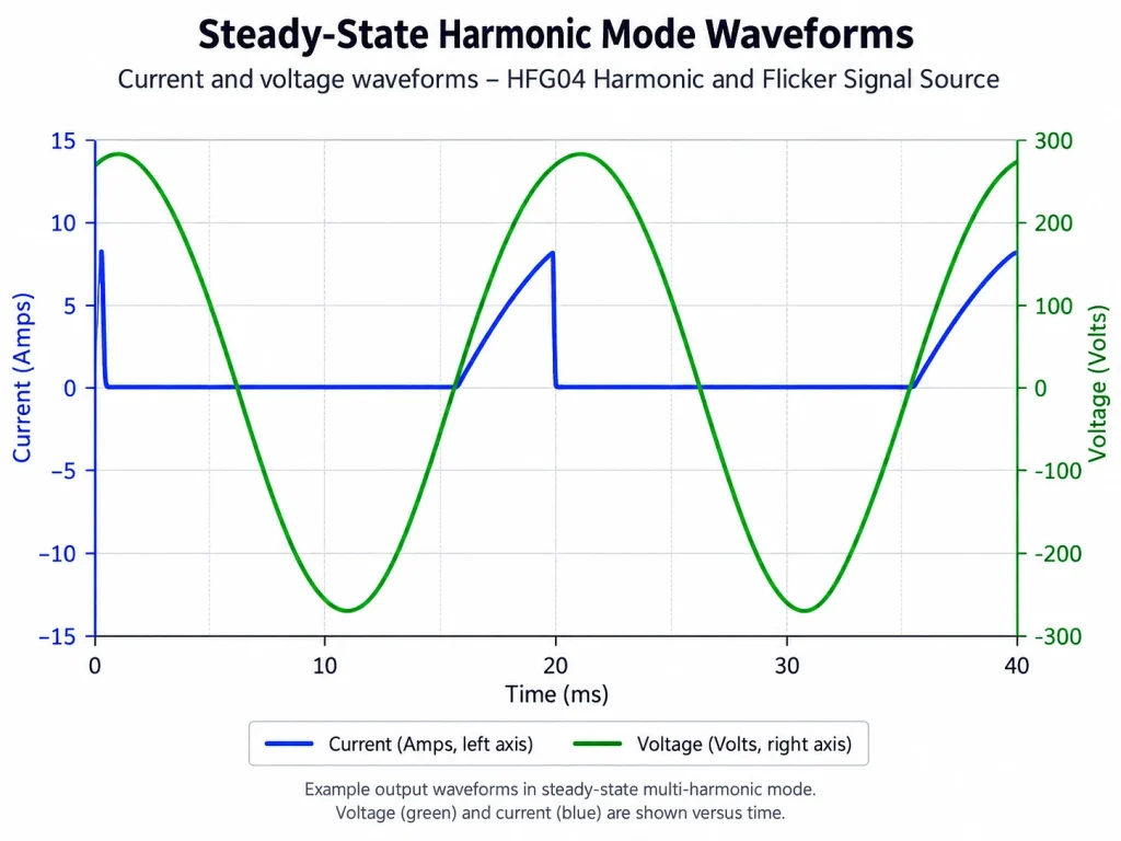
Steady-State Load

Provides a fixed multi-harmonic load condition for repeatability checks, harmonic-current comparison and stable baseline verification.HFG04 steady-state multi-harmonic current and voltage waveform for harmonic measurement system verification
Harmonic

Fluctuating Load

Changes between two load conditions to check whether the measurement system tracks dynamic harmonic-current changes consistently.
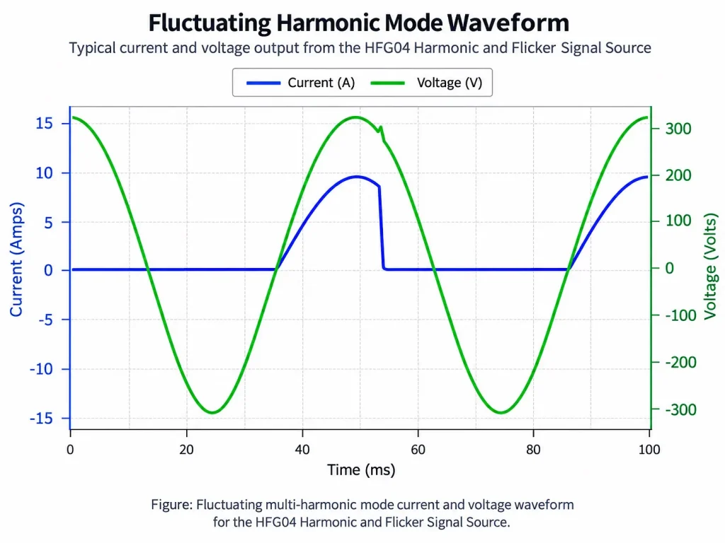
HFG04 fluctuating multi-harmonic load current and voltage waveform for dynamic system verification


Flicker

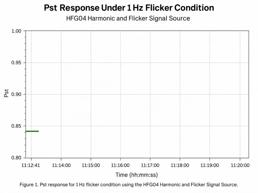
1 Hz Disturbance

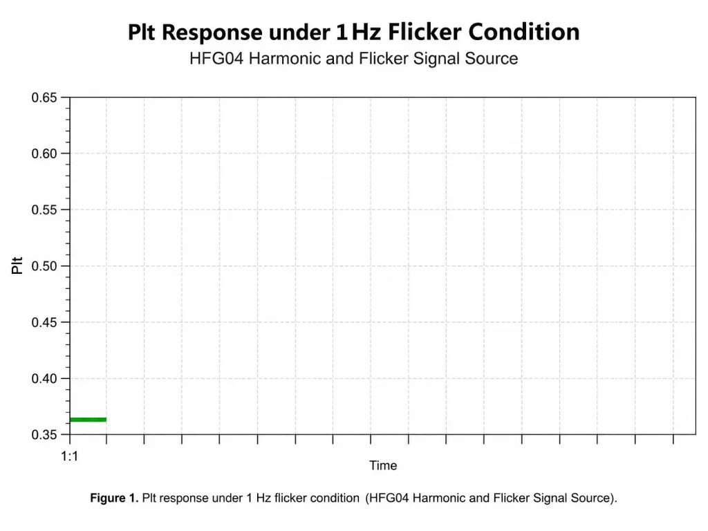
Produces a repetitive load disturbance at one cycle per second for checking voltage-fluctuation and flicker response.HFG04 1 Hz flicker condition Pst response for IEC 61000-3-3 measurement system verificationHFG04 1 Hz flicker condition Plt response for IEC 61000-3-3 system verification
Flicker

8.33 Hz Disturbance

Provides a faster periodic disturbance that produces a different flicker response for comparison with the 1 Hz condition.

Typical Verification Examples

The following values illustrate how different HFG04 modes can produce distinct measurement-system responses. They are application examples, not fixed guaranteed HFG04 output specifications.

Harmonic Verification Examples

Harmonic Mode

HARMONIC SS

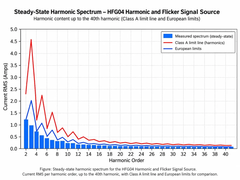
Steady-State

THC

1.977 A

I-THD

136.8%

I RMS

2.483 A

Power Factor

0.420

IEC 61000-3-2:2018/AMD1:2020 Class A example. The recorded system result was Fail, demonstrating a deliberately distinguishable harmonic verification condition.HFG04 steady-state harmonic spectrum showing harmonic components up to the 40th harmonic
Harmonic Mode

HARMONIC FLUCT

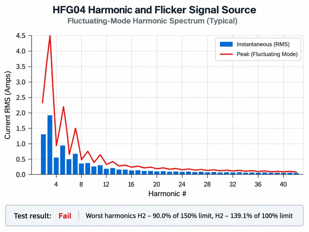
Fluctuating

THC

1.844 A

I-THD

62.4%

I RMS

4.122 A

Power Factor

0.752

IEC 61000-3-2:2018/AMD1:2020 Class A example. The changing load produces a different harmonic-current pattern for dynamic system verification.HFG04 fluctuating-mode harmonic spectrum for IEC 61000-3-2 measurement system verification
Flicker Verification Examples

1 Hz Disturbance


Example: Pass

Vrms 229.18 V
Highest dmax 1.25%
Pst 0.839
Plt 0.366


8.33 Hz Disturbance


Example: Pst Fail

Vrms 227.35 V
Highest dmax 0.74%
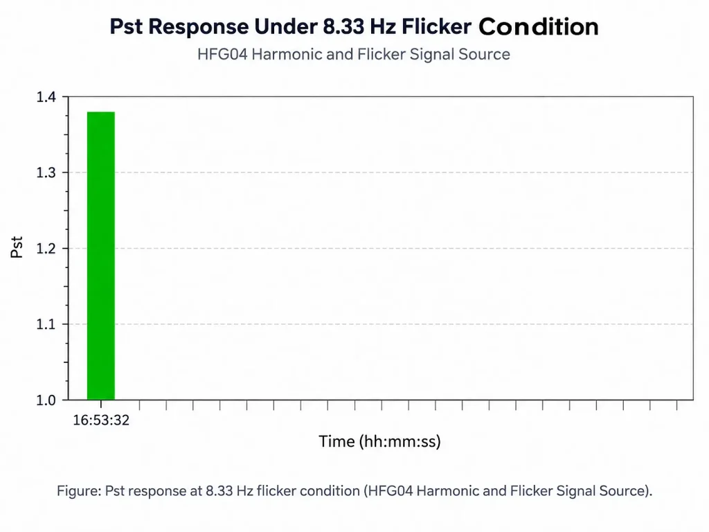
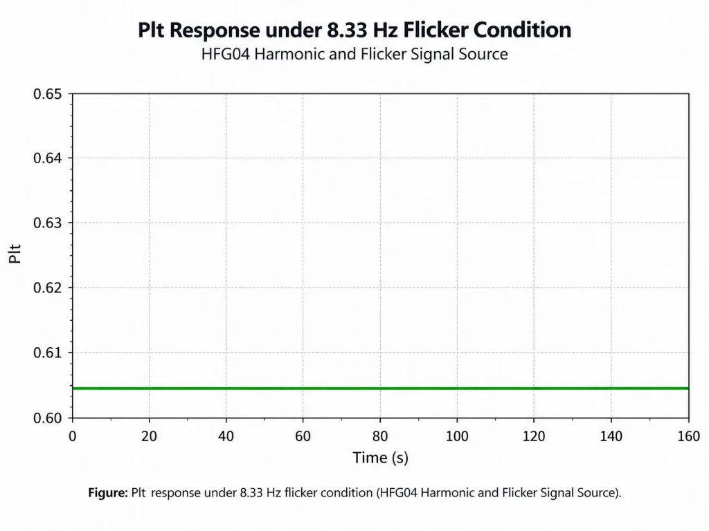
Pst 1.384
Plt 0.605

HFG04 8.33 Hz flicker disturbance Pst response for flickermeter verificationHFG04 8.33 Hz flicker disturbance Plt response for IEC 61000-3-3 measurement verification

The Pass/Fail labels above belong to the illustrated verification conditions. Their value is that the 1 Hz and 8.33 Hz modes produce clearly different measurement-system responses; they should not be treated as guaranteed fixed HFG04 output values.

Typical Laboratory Use

Intermediate System Checks

Repeat an established HFG04 condition between formal calibration intervals to monitor measurement-system consistency.

After Maintenance or Changes

Compare system response before and after analyzer repair, software updates, hardware replacement, wiring changes or relocation.

Troubleshooting Unexpected Results

Check whether an abnormal DUT result is accompanied by a change in the measurement system’s response to a known HFG04 condition.

Long-Term Performance Monitoring

Record the response to the same verification mode over time to identify changes between calibration events.

Cross-System Comparison

Apply the same harmonic or flicker condition to different measurement systems to investigate differences under controlled conditions.

For meaningful comparison, keep the HFG04 operating mode, supply condition, wiring, analyzer settings and measurement procedure consistent.

Applicable Standards and Measurement Scope

Harmonic Current Emissions

IEC 61000-3-2

IEC 61000-3-2 specifies limits for harmonic current emissions from electrical and electronic equipment with rated input current up to and including 16 A per phase.

The current consolidated publication incorporates IEC 61000-3-2:2018, Amendment 1:2020 and Amendment 2:2024, with the applicable Interpretation Sheet.

HFG04 Harmonic Source

IEC 61000-3-2 Measurement System

Response Check

HFG04 supports verification of the measurement system; it does not replace the harmonic analyzer used to evaluate DUT compliance.

Voltage Fluctuations & Flicker

IEC 61000-3-3

IEC 61000-3-3 addresses voltage changes, voltage fluctuations and flicker from equipment with rated current up to 16 A per phase and not subject to conditional connection.

The current consolidated publication incorporates IEC 61000-3-3:2013, Amendment 1:2017 and Amendment 2:2021, with the applicable Interpretation Sheet.

HFG04 Flicker Mode

IEC 61000-3-3 Measurement System

Response Check

HFG04 provides controlled flicker conditions for checking measurement-system response. Confirm the applicable national adoption and edition when a specific laboratory procedure is required.
Compliance & Regulatory Assurance

The HFG04 Harmonic and Flicker Signal Source supports verification of harmonic and flicker analyzers and measurement systems used for IEC / EN 61000-3-2 harmonic-current testing and IEC / EN 61000-3-3 voltage-fluctuation and flicker testing.

It is suitable for routine or intermediate system checks, troubleshooting and performance monitoring. HFG04 does not replace the harmonic analyzer, flickermeter, formal calibration or the complete DUT compliance test system.

Download Datasheet

Download the KingPo HFG04 Harmonic and Flicker Signal Source datasheet for IEC 61000-3-2 harmonic current and IEC 61000-3-3 flicker measurement-system verification, including key specifications, harmonic verification examples, flicker response examples and typical EMC laboratory use cases.


Download Datasheet

Technical Inquiry & Expert Support

For HFG04 selection or system verification support, please provide the following information:

Applicable Standard

IEC / EN / GB standard and edition
Measurement System

Analyzer or flickermeter manufacturer and model
Laboratory Supply
Mains voltage and frequency
Verification Scope

Harmonic verification, flicker verification, or both
KINGPO can assist with configuration review, application matching and documentation requirements before quotation.

Harmonic and Flicker Signal Source for IEC 61000-3-2 / IEC 61000-3-3 System Verification

FAQ

What is a harmonic and flicker signal source?
A harmonic and flicker signal source creates repeatable electrical conditions for checking an existing harmonic measurement system or flickermeter. HFG04 provides multi-harmonic load-current modes and controlled 1 Hz / 8.33 Hz flicker disturbances so laboratories can evaluate whether their measurement systems continue to respond consistently.
Is HFG04 a harmonic analyzer?
No. HFG04 creates the harmonic load condition; the harmonic analyzer measures the resulting current and harmonic spectrum. For DUT compliance testing, the laboratory still requires an appropriate IEC 61000-3-2 measurement system.
Is HFG04 a flickermeter?
No. HFG04 produces controlled load disturbances, while the flickermeter measures the resulting voltage fluctuation and flicker parameters. The two instruments perform complementary functions.
What harmonic modes does HFG04 provide?
HFG04 provides a steady-state multi-harmonic load and a fluctuating multi-harmonic load that changes between two operating conditions. This allows laboratories to verify measurement-system behaviour under both stable and changing harmonic conditions.
What harmonic range does HFG04 cover?
The harmonic function extends through the 40th harmonic, with a stated frequency range of 50 Hz to 2 kHz.
What flicker modes are available?
HFG04 provides controlled disturbances at 1 Hz and 8.33 Hz. The two operating modes create different flicker responses and can therefore be used as repeatable conditions for checking the connected measurement system.
When should a laboratory verify its harmonic or flicker system?
Useful verification points include before important testing, after maintenance or configuration changes, when results appear abnormal, and during periodic equipment checks. The actual interval should be defined by the laboratory's own quality procedure and measurement risk.
Can HFG04 help compare two harmonic measurement systems?
Yes. The same HFG04 operating condition can be measured by two systems to help identify differences in their responses. For valid comparison, the supply, wiring, operating mode, analyzer settings and measurement procedure should remain consistent.
Does HFG04 replace formal calibration?
No. HFG04 is intended for system verification, intermediate checks, troubleshooting and performance monitoring. Formal calibration, traceability and uncertainty evaluation should continue to follow the laboratory's applicable calibration and quality requirements.
Which IEC edition should I specify when ordering?
Specify the exact IEC or national-standard edition currently used by the laboratory. The current IEC 61000-3-2 consolidated publication includes amendments through AMD2:2024, while IEC 61000-3-3 includes amendments through AMD2:2021. Confirming the edition helps ensure the intended verification procedure is appropriate for the laboratory's current test scope.

Related Products

Related News

Different IEC 62368-1 test circuits may require different impulse generator configurations, even when their voltage ranges overlap. A typical request […]

KINGPO IEC 62368-1 Annex G.8.2.2 Varistor Overload Test Equipment streamlines compliance and ensures reliable varistor safety validation.
IEC 62368-1 Annex D.3 impulse test generator ensures lab reliability, precise compliance, and efficient surge testing with advanced safety and automation.
IEC Standards and Definitions ensure global safety, reliability, and compatibility for electrical and electronic products across industries.
Compare KINGPO KP-1060 with top ESD generator and capacitor discharge testers to find the best option for safe, accurate capacitor discharge testing.
Impulse test generator features for IEC 62368-1: dual waveforms, adjustable voltage, and safety controls make compliance and electrical testing simple.

As service robots (Service Robots) are increasingly deployed in commercial, public, and healthcare environments, human-robot interaction safety, mobility-related hazards, and […]

KingPo IP Testing Equipment delivers advanced automation, precise waterproof and dustproof testing, and user-friendly controls for reliable product protection.
Scroll to Top

Get A Free Quote Now !

Contact Form
If you have any questions, please do not hesitate to contact us.