Front view of IEC 62560-1 Figure 8 Test Circuit showing digital display, control knob and connected test lamp in laboratory
Side view of IEC 62560-1 Figure 8 Test Circuit highlighting its compact industrial design
Rear view of IEC 62560-1 Figure 8 Test Circuit showing power input and connection ports

IEC 62560-1 Figure 8 Test Circuit for Non-Dimmable Lamps

The IEC 62560-1 Figure 8 Test Circuit is a specialized test fixture designed to evaluate the safety performance of non-dimmable self-ballasted lamps when they are incorrectly connected to dimmers or electronic switches. This test simulates abnormal operating conditions as specified in IEC 62560-1 Figure 8.

  • Designed according to IEC 62560-1 Figure 8 test circuit requirements
  • Used to test non-dimmable self-ballasted lamps under abnormal dimmer operation
  • Includes key components: potentiometer, Triac, Diac, capacitors, inductor, and RMS ammeter
  • Allows adjustment of current to determine maximum I r.m.s. value
  • Compact design suitable for laboratory use
  • Supports repeatable and standardized abnormal operation testing
  • MOQ: 1 set
  • Delivery Time: 15 working days

IEC 62560-1 Figure 8 Test Circuit Description

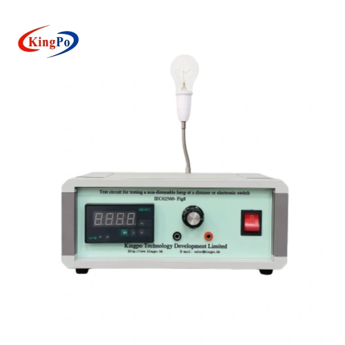
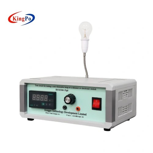
IEC62560-1 Figure 8 Test Circuit For Non-Dimmable Lamp At Dimmer Or Electronic Switch

The IEC 62560-1 Figure 8 Test Circuit is used to assess the behavior of non-dimmable self-ballasted lamps when connected to dimmers or electronic switches. According to IEC 62560-1, such lamps may experience abnormal electrical conditions when used with dimming devices, potentially leading to overheating or failure.

The test circuit allows laboratories to gradually increase the current through the lamp and determine the maximum RMS current the lamp can withstand for a specified duration (typically 60 minutes). If the lamp fails, testing is repeated at a 10% lower current level. This method helps verify the lamp’s safety under misuse conditions involving dimmers.

Technical Parameters

Parameter Specification Remark or Notes
Applicable Standard IEC 62560-1 Figure 8 Abnormal operation test for non-dimmable lamps
Test Purpose Abnormal operation test when non-dimmable lamp is connected to dimmer or electronic switch Evaluates lamp safety under misuse conditions
Test Object Non-dimmable self-ballasted lamps When connected to dimmer or electronic switch
Key Components Potentiometer R1, Triac (BTA16/700), Diac (DB3), Capacitors (C1=100nF, C2=68–150nF), Inductor (L1=3mH), RMS Ammeter, 60W incandescent load Configured per Figure 8 requirements
Test Duration 60 minutes Standard test time per procedure
Current Measurement True RMS (I r.m.s.) Critical parameter for determining maximum withstand current
Test Procedure Gradually increase current to maximum I r.m.s.; reduce by 10% upon failure and retest Follows the step-down method specified in the standard
Power Supply AC 220V, 50Hz Required for ammeter and circuit operation
Application Lamp safety testing under abnormal dimmer use Suitable for quality control and compliance testing


Testing Principle

Schematic diagram of IEC 62560-1 Figure 8 Test Circuit for testing non-dimmable self-ballasted lamps with dimmers or electronic switches.
Test Circuit For Non-Dimmable Lamps

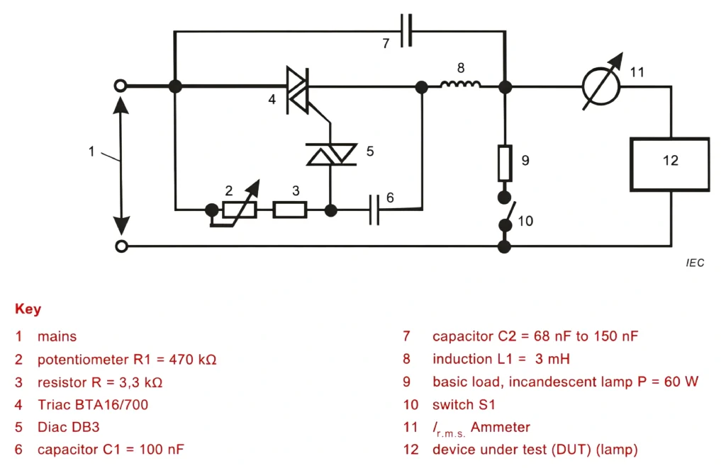
The IEC 62560-1 Figure 8 Test Circuit simulates the abnormal operating condition where a non-dimmable self-ballasted lamp is connected to a dimmer or electronic switch. In such cases, the lamp may be exposed to irregular voltage waveforms and excessive current stress, which can lead to overheating, component damage, or safety risks.

The test circuit uses a potentiometer to gradually adjust the current flowing through the lamp. During the test, the current is increased to determine the maximum RMS value the lamp can withstand for a defined period (typically 60 minutes). If the lamp fails, the current is reduced by 10% and the test is repeated. This method allows laboratories to evaluate the lamp’s safety performance under incompatible dimming conditions in accordance with IEC 62560-1 Figure 8.

Common Error Mitigation

To obtain accurate and reliable test results, the following practices are recommended:

  • Ensure all components (Triac, Diac, capacitors, and inductor) are correctly connected according to IEC 62560-1 Figure 8.
  • Use a properly calibrated RMS ammeter for accurate current measurement.
  • Follow the correct procedure of testing at maximum current first, then reducing by 10% if failure occurs.
  • Maintain stable laboratory power supply during testing.
  • Regularly inspect and replace components that may degrade over time.

Applications and Use Cases

Non-dimmable lamp test circuit secured inside aluminum transport case
IEC 62560-1 Figure 8 Test Circuit Stored in Aluminum Carry Case

The IEC 62560-1 Figure 8 Test Circuit is mainly used by lamp manufacturers and third-party testing laboratories.

Typical applications include:

  • Safety testing of non-dimmable self-ballasted lamps under abnormal dimmer operation
  • Compliance verification according to IEC 62560-1 Figure 8
  • Quality control testing for LED and CFL lamps
  • Evaluation of lamp behavior when used with incompatible dimmers or electronic switches
  • Pre-compliance testing before formal certification

Key Advantages

The IEC 62560-1 Figure 8 Test Circuit provides a standardized and practical method to evaluate the safety of non-dimmable self-ballasted lamps under abnormal operating conditions caused by dimmers or electronic switches. By replicating the electrical stress these lamps may encounter in real use, it helps manufacturers identify potential safety risks such as overheating or component failure at an early stage.

Its compact design and clearly defined components make the circuit easy to set up and operate in laboratory environments. Compared with more complex testing systems, this test circuit offers a cost-effective solution for compliance testing according to IEC 62560-1 Figure 8, while delivering consistent and repeatable results essential for quality control and product development.

Compliance & Regulatory Assurance

This test circuit is designed in accordance with IEC 62560-1 Figure 8 to evaluate the safety of non-dimmable self-ballasted lamps when used with dimmers or electronic switches under abnormal conditions.

Metrological Integrity & Validation

  • Regular verification of the RMS ammeter accuracy is recommended.
  • Components such as the Triac and capacitors should be inspected periodically for performance consistency.
  • Proper setup and connection according to the standard diagram helps ensure repeatable test results.

Download Product Documentation

Technical Inquiry & Expert Support

KingPo supplies the IEC 62560-1 Figure 8 Test Circuit for abnormal operation testing of non-dimmable lamps. Our team can provide guidance on test setup, component configuration, and test procedures according to IEC 62560-1 Figure 8.

For technical specifications or quotations, please contact us with your testing requirements.

IEC 62560-1 Figure 8 Test Circuit for Non-Dimmable Lamps

IEC 62560-1 Figure 8 Test Circuit for Non-Dimmable Lamps FAQs

What is the purpose of the IEC 62560-1 Figure 8 Test Circuit?
The IEC 62560-1 Figure 8 Test Circuit is used to evaluate the safety performance of non-dimmable self-ballasted lamps when they are connected to dimmers or electronic switches. It simulates abnormal operating conditions to determine whether the lamp can withstand the resulting electrical stress without overheating or failure.
Which standard does this test circuit comply with?
This test circuit is designed in accordance with IEC 62560-1 Figure 8. It provides a standardized method to assess the behavior of non-dimmable lamps under abnormal conditions caused by connection to dimmers or electronic switches.
What type of lamps can be tested with this circuit?
The test circuit is intended for non-dimmable self-ballasted lamps, including LED and CFL lamps. It is used to check their safety when incorrectly used with dimming devices, which is considered an abnormal operating condition under IEC 62560-1.
Why is it necessary to test non-dimmable lamps with dimmers?
Although non-dimmable lamps are not designed for use with dimmers, they may be incorrectly connected in practice. This test evaluates whether the lamp remains safe under such conditions, helping to prevent potential overheating, fire hazards, or premature failure.
How does the IEC 62560-1 Figure 8 test work?
The test circuit uses a potentiometer to gradually increase the current through the lamp. The lamp is tested at the maximum RMS current for a defined period, usually 60 minutes. If failure occurs, the current is reduced by 10% and the test is repeated to determine the safe operating limit.
What happens if the lamp fails during the test?
If the lamp fails at the maximum test current, the current is reduced by 10% and the test is repeated. This step-down procedure helps identify the highest current level at which the lamp can operate safely without failure under abnormal dimmer conditions.
Who typically uses the IEC 62560-1 Figure 8 Test Circuit?
This test circuit is mainly used by lamp manufacturers, lighting testing laboratories, and certification bodies. It supports quality control, product development, and compliance verification for non-dimmable self-ballasted lamps according to IEC 62560-1 requirements.
Is this test required for lamp certification?
Yes. Many certification schemes and safety standards require testing of non-dimmable lamps under abnormal conditions when used with dimmers. The IEC 62560-1 Figure 8 Test Circuit provides a standardized method to meet these safety evaluation requirements.
What are the main components of this test circuit?
The test circuit typically includes a potentiometer, Triac, Diac, capacitors, an inductor, an RMS ammeter, and a basic load. These components are configured according to the circuit diagram specified in IEC 62560-1 Figure 8.
How should this test circuit be maintained?
Regular inspection of key components such as the Triac, capacitors, and RMS ammeter is recommended to ensure accurate and repeatable results. Proper connection according to the standard diagram and periodic calibration of the ammeter help maintain test reliability.

Related Products

Related News

KingPo UV Test Chamber offers advanced UV simulation, precise control, and high capacity for reliable, standards-compliant material testing.
Professional thermal shock testing chambers ensure reliable, repeatable results, helping manufacturers detect weaknesses and improve product durability.
Choose the right IPX8 water immersion test chamber by focusing on compliance, reliability, and features that match your product’s water resistance requirements.
IK Rating Testing Technology and Application Based on KINGPO IK01‑06 Spring Impact Hammer ensures precise impact resistance assessment for electrical enclosures.

Key Takeaways A tensile strength testing machine evaluates the mechanical properties of plastics and other materials under controlled tension, providing […]

Meet UL94 and IEC standards with the horizontal vertical flame tester. Follow step-by-step testing and compliance procedures for reliable fire safety results.

IPX9K represents one of the highest levels of water ingress protection in the IEC 60529 and ISO 20653 standards. It […]

In the realm of electrical safety, where materials must endure potential fire risks, the Kingpo KP-FT01 Glow Wire Tester emerges […]

Scroll to Top

Get A Free Quote Now !

Contact Form
If you have any questions, please do not hesitate to contact us.