Mechanical impact resistance is a fundamental consideration in the safety assessment of electrical and electronic equipment. External mechanical forces can damage enclosures, displace protective components, compromise insulation barriers, or expose hazardous parts even when the equipment continues to operate normally.
For manufacturers and testing laboratories, mechanical impact testing is therefore not simply a measure of enclosure durability. It is an evaluation of whether equipment maintains the required level of protection after exposure to specified mechanical stresses.
Two international standards are particularly relevant to this assessment: IEC 60068-2-75, which establishes standardized hammer impact test methods, and IEC 62262, which defines the IK classification system for protection against external mechanical impacts.
Understanding the relationship between these standards, their test methods, and the applicable product safety requirements is essential for obtaining repeatable and technically defensible results.
Mechanical Impact Testing: What Is Actually Being Evaluated?
Mechanical impact testing applies a controlled, short-duration mechanical load to a specimen to evaluate its response under defined conditions.
Depending on the product and applicable standard, the assessment may address several aspects of enclosure integrity:
- Resistance to cracking, fracture, and permanent deformation.
- Retention of protective covers, barriers, and structural components.
- Prevention of access to hazardous live or moving parts.
- Preservation of the required degree of protection against environmental ingress.
- Maintenance of safety-related functions following mechanical stress.
An important distinction is that visible damage does not necessarily constitute failure, and the absence of visible damage does not necessarily demonstrate compliance.
For example, an enclosure may show minor surface deformation while retaining its protective function. Conversely, an apparently undamaged enclosure may have suffered displacement of an internal barrier or damage to an electrical insulation component.
Acceptance must therefore be established against the requirements of the relevant product standard rather than appearance alone.
IEC 60068-2-75: Standardized Hammer Impact Test Methods
IEC 60068-2-75, Environmental testing – Part 2-75: Tests – Test Eh: Hammer tests, establishes three coordinated methods for applying specified mechanical impacts.
The consolidated edition IEC 60068-2-75:2014+A1:2025 covers nominal impact energies from 0.14 J to 50 J.
The three methods are:
| Test method | Designation | Basic principle |
|---|---|---|
| Pendulum hammer | Test Eha | A suspended striking element impacts the specimen after release |
| Spring hammer | Test Ehb | A spring mechanism delivers a calibrated mechanical impact |
| Vertical hammer | Test Ehc | A striking element falls vertically onto the specimen |
These methods share the objective of applying a defined impact severity, but their mechanical arrangements and practical applications differ.
The selection of an appropriate method depends on the relevant standard, required impact energy, specimen geometry, impact direction, and mounting conditions.
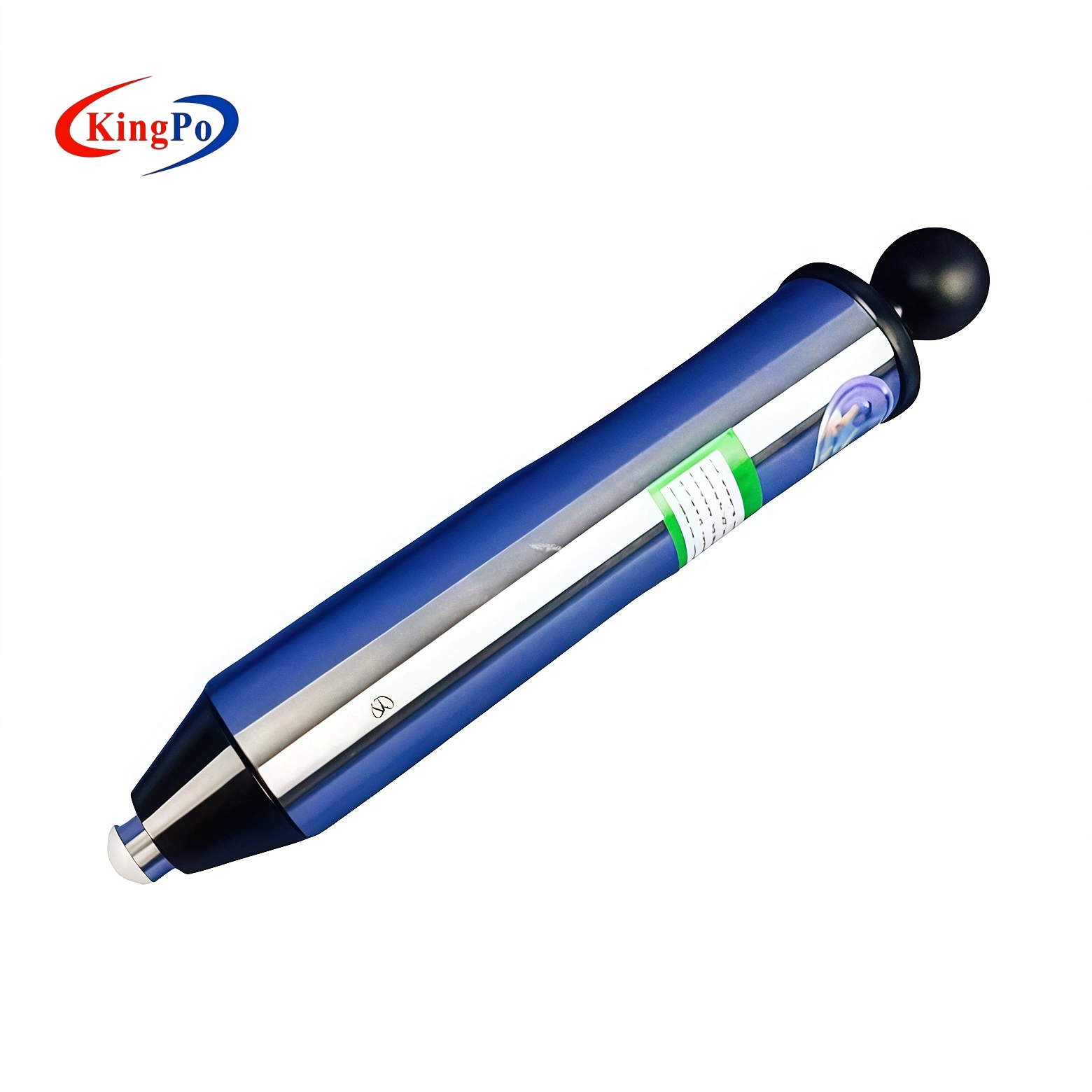
Spring-Operated Impact Hammer — Test Ehb
The spring-operated impact hammer is widely used for evaluating the mechanical strength of relatively small electrical enclosures and accessible components.
Its operating mechanism stores energy in a spring. When the release mechanism is activated, the striking element moves forward and delivers the selected impact energy to the test surface.
Unlike gravitational impact arrangements, the spring hammer does not rely on the release height of a suspended or falling mass.
This makes it particularly useful for impact locations where a conventional pendulum apparatus may be difficult to position.
Typical applications include electrical accessories, household appliances, luminaires, and equipment enclosures.
For these applications, the KINGPO IEC 60068-2-75 Spring Impact Hammer provides selectable impact energies of 0.14 J, 0.2 J, 0.35 J, 0.5 J, 0.7 J, and 1.0 J for standardized mechanical strength testing.
Engineering considerations
The accuracy and repeatability of a spring hammer test depend on more than the nominal energy setting.
The striking element geometry, spring characteristics, release mechanism, and positioning relative to the test surface can influence the applied impact.
The hammer should be operated according to the specified procedure, with particular attention to the impact direction and release conditions.
For irregular or recessed surfaces, sufficient access must be available to position the striking element correctly without unintended interference from adjacent structures.
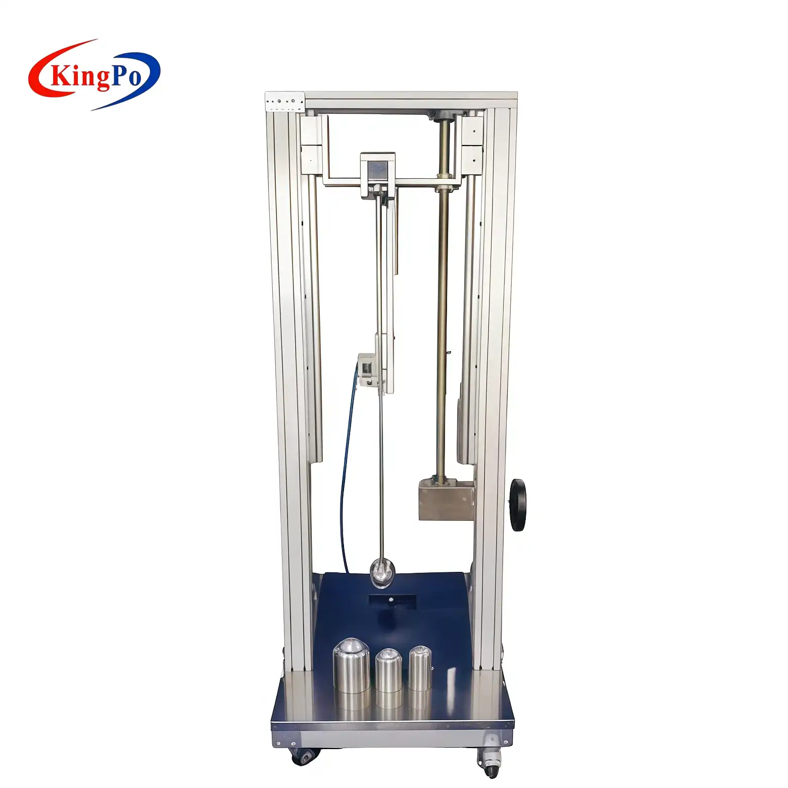
Pendulum Impact Hammer — Test Eha
Pendulum impact testing uses a striking element suspended from a pivot. The hammer is raised to a defined position and released to strike the specimen.
The nominal impact energy is related to the effective mass and vertical displacement of the striking element:
E = mgh
Where:
- E = impact energy, expressed in joules (J).
- m = effective mass, expressed in kilograms (kg).
- g = gravitational acceleration (m/s²).
- h = vertical displacement of the center of mass (m).
Although this equation describes the fundamental energy relationship, standardized impact testing requires additional control of the striking element and apparatus.
The effective mass, striking face geometry, hardness, release arrangement, and dimensional requirements must correspond to the prescribed test configuration.
Two pendulum hammers delivering the same nominal energy cannot automatically be considered equivalent if their striking elements have different contact geometries.
This is especially relevant for electrical enclosures made from polymers, sheet metal, or composite materials, where local stress concentration can significantly influence cracking and deformation.
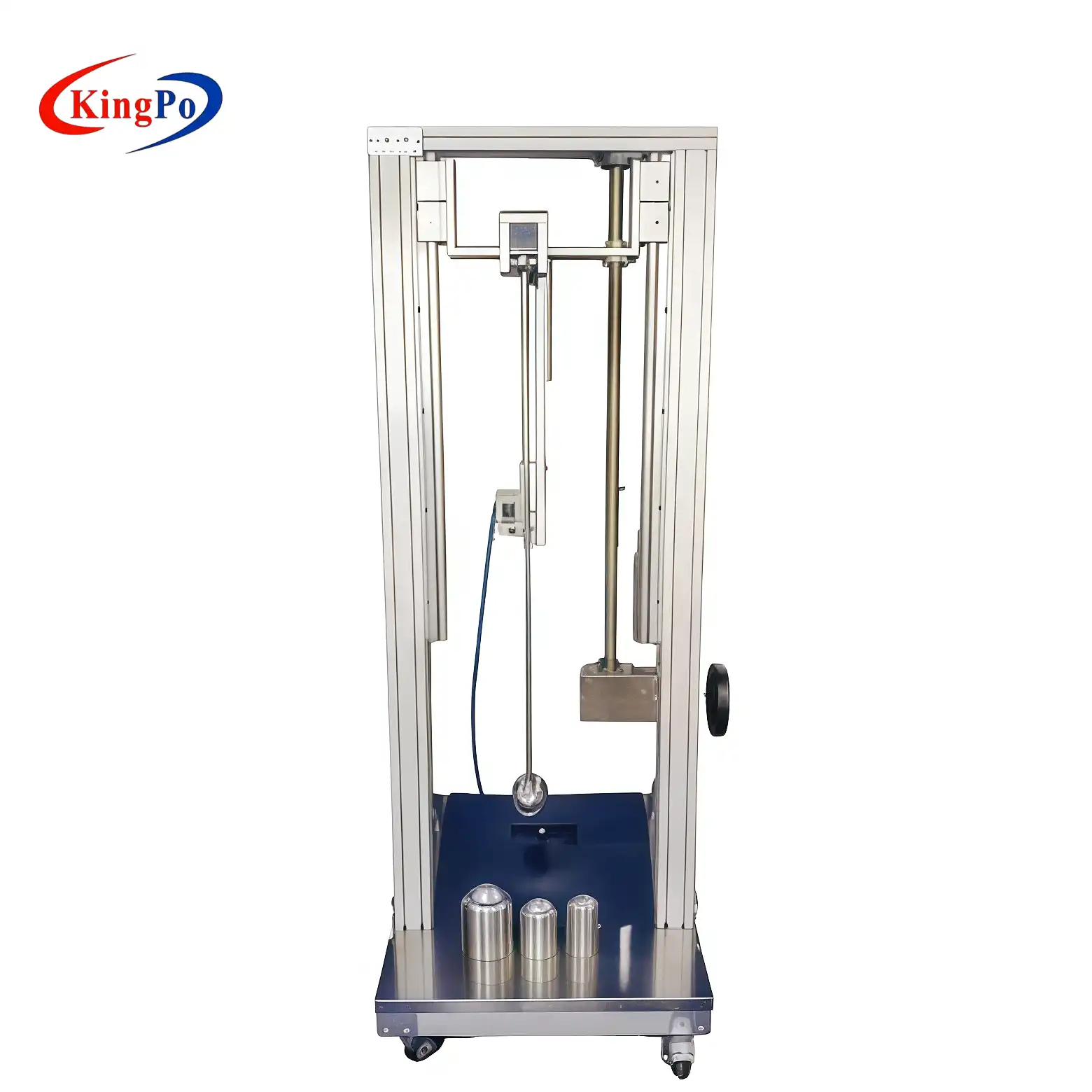
For enclosure testing at higher impact energies, the KINGPO IEC 60068-2-75 Pendulum Impact Hammer supports interchangeable striking configurations for 2 J, 5 J, 10 J, 20 J, and 50 J testing.
Vertical Hammer — Test Ehc
Vertical hammer testing applies an impact by allowing a striking element to fall vertically onto the specimen.
The method is particularly relevant when the test surface and mounting configuration permit an impact along the vertical axis.
As with pendulum testing, the prescribed energy depends on the effective mass and release height, but these parameters must be established using the standardized apparatus requirements.
Vertical hammer testing requires particular attention to:
- Vertical alignment of the striking element.
- Stability and rigidity of the specimen support.
- Accurate control of the release height.
- Prevention of unintended contact during the fall.
- Correct striking element geometry and mass.
A vertical hammer arrangement is not necessarily a substitute for a pendulum arrangement simply because the two systems are capable of delivering identical nominal energies.
The applicable test method must be established from the relevant requirements.
IEC 62262: Understanding the IK Classification System
IEC 62262, Degrees of protection provided by enclosures for electrical equipment against external mechanical impacts (IK code), establishes a standardized classification system for the mechanical impact protection provided by electrical equipment enclosures.
While IEC 60068-2-75 defines methods for applying impacts, IEC 62262 establishes the relationship between an IK classification and its corresponding impact energy.
This distinction is important:
IEC 60068-2-75 defines how a specified impact is applied. IEC 62262 defines the degree of enclosure protection represented by an IK code.
The two standards are complementary but serve different purposes.
For practical enclosure testing, an IEC 62262 Pendulum Impact Tester can apply controlled impacts using the specified energy level and striking element. The required test configuration must follow the relevant edition of IEC 62262 and any applicable product-specific requirements.
IK Rating and Impact Energy
The classification in IEC 62262:2002+A1:2021 includes the following impact energy levels:
| IK classification | Impact energy |
|---|---|
| IK00 | No specified protection |
| IK01 | 0.14 J |
| IK02 | 0.20 J |
| IK03 | 0.35 J |
| IK04 | 0.50 J |
| IK05 | 0.70 J |
| IK06 | 1 J |
| IK07 | 2 J |
| IK08 | 5 J |
| IK09 | 10 J |
| IK10 | 20 J |
| IK11 | 50 J |
 The 2021 amendment introduced IK11 at 50 J, extending the classification beyond IK10.
However, an IK classification is not an unrestricted statement of impact resistance.
The rating applies to the degree of protection evaluated under the specified test conditions. It does not establish that the enclosure can withstand every possible collision or impact involving the same nominal energy.
Why Equal Impact Energy Does Not Always Mean Equal Damage
Impact energy is only one parameter influencing the mechanical response of an enclosure.
The contact conditions between the striking element and the specimen can substantially affect the resulting stress distribution.
Striking face geometry
A smaller contact area can produce higher localized contact stress, potentially increasing the likelihood of cracking or penetration.
Enclosure material
Ductile metals, brittle polymers, and reinforced composite materials may exhibit substantially different responses under the same nominal impact conditions.
Mounting and support conditions
A flexible mounting arrangement may allow greater global movement, while a rigid support can change the local stress distribution.
Impact location
Corners, joints, door hinges, transparent panels, fastening points, and areas with reduced wall thickness may be more susceptible to damage than continuous flat surfaces.
Temperature and conditioning
Material impact performance can change with temperature, aging, and environmental exposure. Where conditioning is specified, it forms part of the test requirements.
Consequently, an impact test should not be reduced to a comparison of numerical energy values.
The entire prescribed test configuration must be considered.
IEC 62262 IK Ratings vs. IEC 60529 IP Ratings
IK and IP classifications are often discussed together because both concern protective enclosures. However, they evaluate different characteristics.
| Classification | Standard | Assessment |
|---|---|---|
| IK | IEC 62262 | Protection against external mechanical impacts |
| IP | IEC 60529 | Protection against access, solid foreign objects, and water ingress |
An enclosure rated IP65 is not necessarily resistant to a 20 J mechanical impact.
Similarly, an IK10 enclosure does not automatically satisfy any particular IP classification.
The relationship becomes particularly important after mechanical impact testing.
An impact may deform a door, damage a sealing surface, or displace a gasket without causing complete structural failure.
Where the applicable requirements demand preservation of an IP classification, the post-impact evaluation must consider whether the specified ingress protection has been impaired.
For equipment requiring both mechanical impact resistance and environmental protection, the test plan should address these requirements together.
Mechanical Impact Requirements in Product Safety Standards
IEC 60068-2-75 and IEC 62262 provide a technical foundation, but the applicable product standard often determines the actual test severity and evaluation criteria.
Household and Similar Electrical Appliances — IEC 60335 Series
IEC 60335-1 establishes general safety requirements for household and similar electrical appliances.
Mechanical strength testing is relevant because damage to an appliance enclosure may create access to live parts, moving components, or other hazards.
Depending on the product category, the applicable IEC 60335-2 particular standard may introduce additional conditions or modify the general requirements.
Therefore, engineers should establish the test configuration using the applicable edition of IEC 60335-1 together with the relevant particular standard.
A spring-operated impact hammer may be suitable for specified mechanical strength tests, but the required energy, impact points, specimen preparation, and acceptance criteria must be determined from the applicable clauses.
Luminaires — IEC 60598 Series
Luminaires may contain protective covers, lenses, optical assemblies, electrical compartments, and mounting structures with different mechanical characteristics.
Mechanical impact testing may be necessary to evaluate whether these components maintain the required safety functions after impact.
For example, a cracked protective cover may require further investigation to determine whether access to hazardous components has become possible.
Impact location and specimen mounting are particularly important for luminaires with glass or polymer covers.
Audio/Video and Information Technology Equipment — IEC 62368-1
IEC 62368-1 uses a hazard-based approach to equipment safety.
Mechanical strength evaluations may involve several different test arrangements, including impact and drop testing, depending on the equipment construction and applicable requirements.
The specified arrangement must be followed rather than substituting a different impact device solely on the basis of nominal energy equivalence.
This distinction is important when comparing steel-ball impact tests with standardized hammer impact tests.
EV Charging Equipment and Large Electrical Enclosures
EV charging equipment presents additional challenges because the specimen may be large, heavy, and intended for wall-mounted, pedestal-mounted, or freestanding installation.
The mounting method and test apparatus must allow the required impact energy to be applied at the specified locations.
Impact testing may need to consider charging station doors, external housings, protective panels, control compartments, and other exposed structural elements.
A movable impact test apparatus can be useful for positioning the striking element relative to large specimens without repeatedly relocating the complete installation.
For these applications, the KINGPO EV Charger Pendulum Impact Tester integrates pendulum hammer and vertical hammer test configurations with nominal impact energies of 2 J, 5 J, 10 J, 20 J, and 50 J. Its adjustable arrangement is particularly relevant to the mechanical strength evaluation of EV charging equipment and other large electrical enclosures.
The relevant product standard and required test arrangement determine which configurations are applicable.
How to Select the Appropriate Impact Testing Apparatus
When specifying a mechanical impact testing system, the maximum available impact energy should not be the only selection criterion.
A technically appropriate configuration should address the following considerations.
Applicable Test Standard
Identify whether the requirement concerns an IEC 60068-2-75 hammer test, an IEC 62262 IK classification, or a mechanical strength test defined by another product standard.
Some product standards specify dedicated impact arrangements that are not interchangeable with the general hammer tests.
Required Impact Energy
Determine the energy level from the applicable clause or classification requirement.
The selected apparatus must provide the prescribed nominal energy with the appropriate striking element and test configuration.
Striking Element Characteristics
Verify the required effective mass, material, striking face geometry, and relevant dimensional tolerances.
Matching impact energy without matching the striking element characteristics may invalidate the intended test configuration.
Specimen Dimensions and Accessibility
Determine whether the apparatus can reach the specified impact locations while maintaining the required direction.
Large enclosures may need adjustable frames, movable supports, or dedicated mounting fixtures.
Mounting and Support Arrangement
The fixture must provide the installation or support conditions required by the test procedure.
Uncontrolled movement, excessive fixture flexibility, and unrealistic restraint can influence the mechanical response.
Equipment Verification and Traceability
The equipment should be subject to appropriate verification of its relevant mechanical characteristics.
Depending on the apparatus, this may include impact energy, striking element mass and dimensions, release height, alignment, and spring hammer performance.
Calibration and verification records should identify the equipment configuration and applicable acceptance limits.
Practical Testing Procedure and Result Evaluation
A structured test procedure improves repeatability and makes the results easier to review during product development, internal quality control, and third-party conformity assessment.
Establish the Test Requirements
Identify the applicable standard edition, test clause, impact severity, number of impacts, required locations, directions, and specimen conditioning.
Acceptance criteria should be defined before testing begins.
Prepare the Specimen
Inspect the specimen and record its initial condition.
Mount the equipment according to the specified arrangement, including any requirements relating to normal installation, mounting brackets, covers, and support structures.
Verify the Test Arrangement
Confirm that the selected striking element, impact energy, and apparatus configuration correspond to the required procedure.
Check that the intended impact points are accessible and that the release mechanism can operate without interference.
Apply the Prescribed Impacts
Apply the specified number of impacts at the required locations.
Avoid introducing unintended variations in release conditions or specimen positioning.
Where the procedure requires impacts at different points or directions, each condition should be documented.
Examine the Specimen
After testing, assess the specimen against the applicable acceptance criteria.
The assessment may include:
- Cracking, fracture, and permanent deformation.
- Separation or displacement of protective components.
- Access to hazardous parts.
- Damage to insulation or internal safety barriers.
- Changes affecting the required IP protection.
- Functional or electrical safety checks where required.
The report should distinguish observed damage from the final compliance determination.
Common Causes of Non-Repeatable or Invalid Test Results
Even when the nominal impact energy is correct, results may be affected by an unsuitable test arrangement.
Incorrect hammer selection. Using a striking element with a different geometry or mass distribution can change the mechanical response.
Unrepresentative mounting. Differences in support rigidity or installation conditions may lead to inconsistent results between laboratories.
Incorrect impact location. Striking near structural supports or previously damaged areas may affect the severity of the test.
Release mechanism interference. Friction, obstruction, or uncontrolled release conditions can alter the delivered impact.
Inadequate equipment verification. Unverified spring mechanisms, hammer masses, or release heights introduce uncertainty into the test severity.
Incomplete post-impact assessment. Focusing only on visible cracks may overlook damage to protective functions.
These factors should be addressed through apparatus verification, documented procedures, and consistent specimen preparation.
Conclusion
Mechanical impact testing is a critical part of electrical equipment safety evaluation, but reliable results depend on more than delivering a specified number of joules.
IEC 60068-2-75 establishes standardized hammer impact methods, while IEC 62262 provides the IK classification system for enclosure protection against external mechanical impacts.
The applicable product standard determines how these requirements are implemented for a particular equipment category, including test severity, specimen preparation, impact locations, and acceptance criteria.
For engineers and testing laboratories, the essential principle is to evaluate the complete test arrangement: impact energy, striking element characteristics, mounting conditions, impact direction, and post-impact safety performance.
A properly selected and verified test system, combined with a clearly documented procedure, provides a sound basis for evaluating enclosure mechanical strength and demonstrating compliance with applicable safety requirements.