KINGPO ENGINEERING INSIGHT
Motor Locked-Rotor Testing Under IEC 60335-1 Clause 19.7
Understanding abnormal operating conditions, winding temperature assessment and electrical safety verification for motor-operated household appliances.
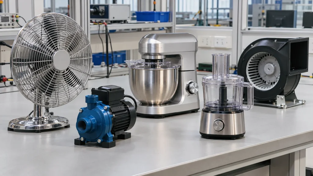
Electric motors are widely used in household and similar electrical appliances, including fans, water pumps, kitchen machines and air circulation systems. During normal operation, these motors are designed to operate within defined electrical and thermal limits. However, a mechanical obstruction, jammed component or unexpected load condition can prevent the motor from rotating.
When a motor stalls, its current consumption and heat generation can change significantly. If the appliance continues operating under this abnormal condition, excessive temperatures may develop in the motor windings and surrounding components, potentially affecting insulation, protective devices and overall product safety.
To evaluate these risks, IEC 60335-1 Clause 19.7 specifies a stalled-condition test for applicable motor-operated appliances. Commonly referred to as a locked-rotor test, this assessment examines whether the appliance remains safe when its motor or relevant moving parts are prevented from operating normally.
This article explains the test principle, applicable motor configurations, laboratory setup, testing procedure and winding temperature evaluation, with reference to the abnormal operation requirements of IEC 60335-1.
Why Is Locked-Rotor Testing Important for Motor-Operated Appliances?
A locked-rotor condition represents a mechanical fault in which a motor or driven component cannot rotate as intended. This may occur when an impeller is blocked, a rotating shaft becomes jammed, a transmission mechanism is obstructed or a moving component encounters an abnormal mechanical load.
Under normal operation, a motor converts electrical energy into mechanical output while dissipating the heat generated in its windings and other components. When rotation is prevented, the operating condition changes and the motor may experience sustained electrical and thermal stress.
Depending on the motor design and its protection arrangement, the resulting effects may include:
- Increased winding temperature caused by abnormal current and reduced cooling.
- Thermal stress on winding insulation and internal electrical connections.
- Operation of thermal protectors, overcurrent protection or other protective devices.
- Potential damage to components or deterioration of electrical insulation.
- Safety hazards if the appliance cannot safely withstand the abnormal operating condition.
The purpose of Clause 19.7 is not simply to determine whether a motor can withstand being stopped. It is to evaluate the safety of the complete appliance under the specified stalled operating conditions, including the effectiveness of its protective arrangements.
Understanding the Locked-Rotor Test Under IEC 60335-1 Clause 19.7
IEC 60335-1 requires the appliance to be operated under stalled conditions. The method used to establish this condition depends on the motor and appliance construction.
The standard identifies two locking approaches:
Rotor locking: For appliances in which the locked-rotor torque is smaller than the full-load torque, the motor rotor is locked to prevent rotation.
Moving-part locking: For other appliances, the relevant moving parts are locked to establish the stalled operating condition.
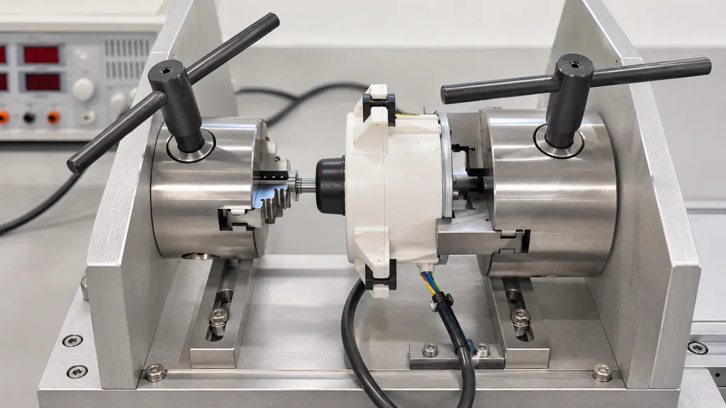
Where an appliance contains more than one motor, the test is carried out separately for each motor.
This distinction is important when designing a test fixture. A universal clamping arrangement may not be suitable for every motor configuration. The locking method must reflect the actual mechanical construction and the applicable test requirements.
For additional information about the broader IEC 60335-1 safety testing requirements, laboratories should also consider the related electrical, thermal, mechanical and abnormal operation assessments specified throughout the standard.
Which Motors and Appliances Are Covered?
Locked-rotor testing is relevant to applicable motor-operated appliances covered by IEC 60335-1. The specific test method depends on the motor construction, appliance function and applicable product-specific requirements.
Examples of appliances incorporating motors that may require evaluation under the relevant abnormal operation provisions include:
| Appliance Type | Typical Motor Application | Potential Abnormal Condition |
|---|---|---|
| Electric Fans | Fan motor and impeller | Blocked impeller or shaft |
| Water Pumps | Pump drive motor | Jammed rotating components |
| Kitchen Machines | Mixing and driving mechanisms | Blocked blades or drive mechanisms |
| Air Circulation Systems | Air-moving motor assemblies | Restricted or stalled rotation |
| Appliance Cooling Fans | Cooling fan motors | Fan blade obstruction |
Single-phase induction motors, including capacitor-run and split-phase configurations, are common examples in household appliances. However, Clause 19.7 should not be interpreted as applying exclusively to this motor category. Other motor designs must be assessed according to their construction and the relevant clauses.
For example, appliances incorporating series motors have a separate abnormal operation test under Clause 19.10. The applicable requirements should therefore be identified from the actual motor design rather than assuming that every motor-operated appliance follows an identical locked-rotor procedure.
It is also important to review the relevant appliance-specific IEC 60335-2 requirements. Part 2 standards may introduce additional or modified test conditions for particular appliance categories.
Setting Up a Locked-Rotor Test
A reliable locked-rotor test requires more than a power source and a mechanical locking device. The laboratory must establish a controlled electrical and mechanical test environment while ensuring that temperature measurements and post-test safety checks can be performed correctly.
A typical laboratory configuration may include the following equipment:
| Equipment | Purpose in the Test |
|---|---|
| AC Power Supply | Provides the specified rated voltage and frequency with sufficient capacity for the motor’s stalled operating current. |
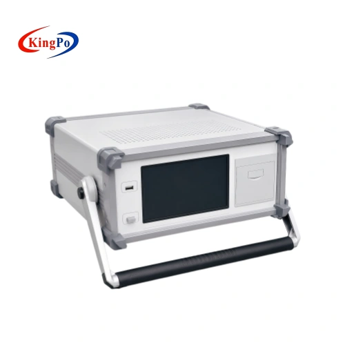
| Temperature Recorder | Records temperature changes at selected monitoring points throughout the test. |
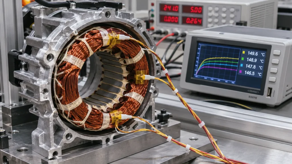
| Thermocouples | Monitor winding or other relevant component temperatures where thermocouple measurement is appropriate. |
| Winding Resistance Measurement System | Determines winding temperature by the resistance method where applicable. |
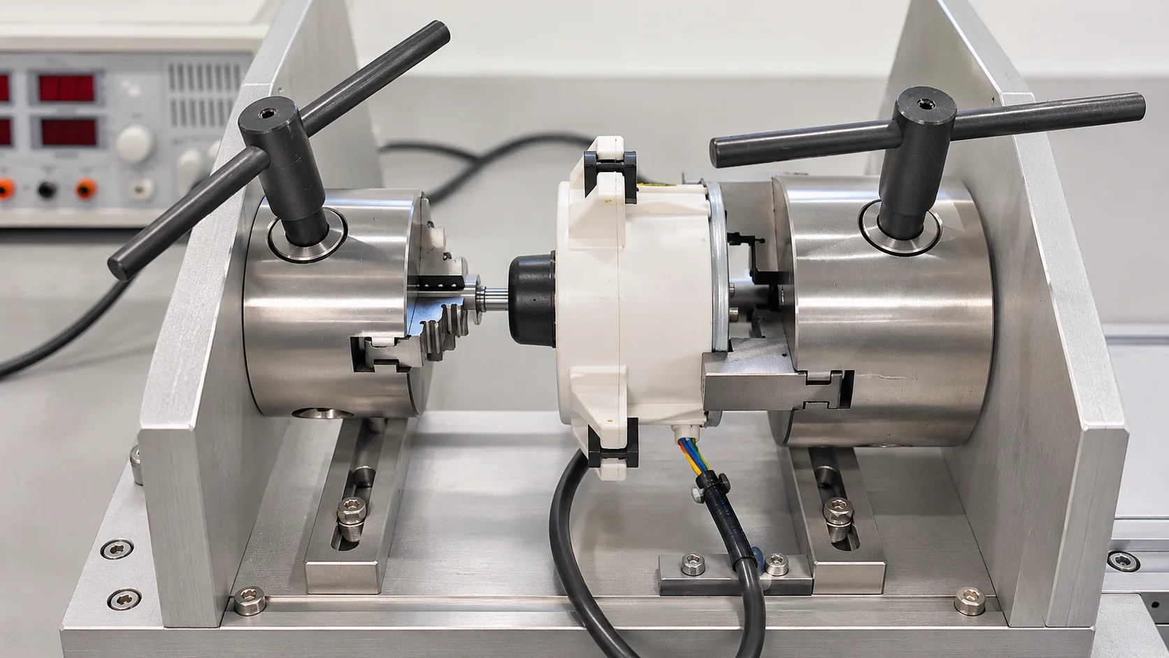
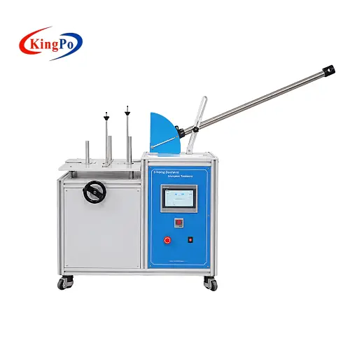
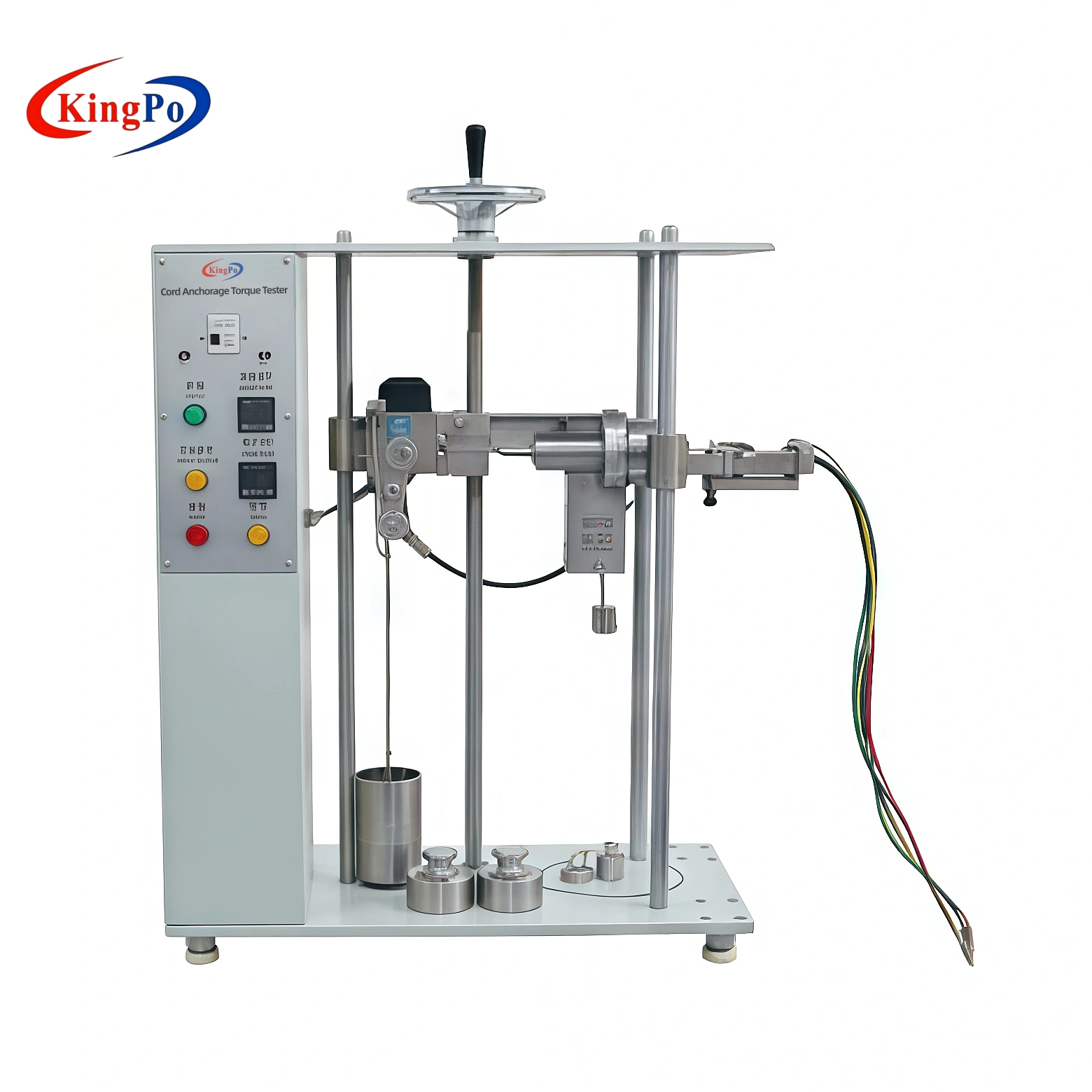
| Locked-Rotor Fixture | Securely locks the motor rotor or relevant moving parts without unintentionally changing the required test configuration. |
| Electrical Measurement Instruments | Monitor voltage, current and power to document the electrical operating condition. |
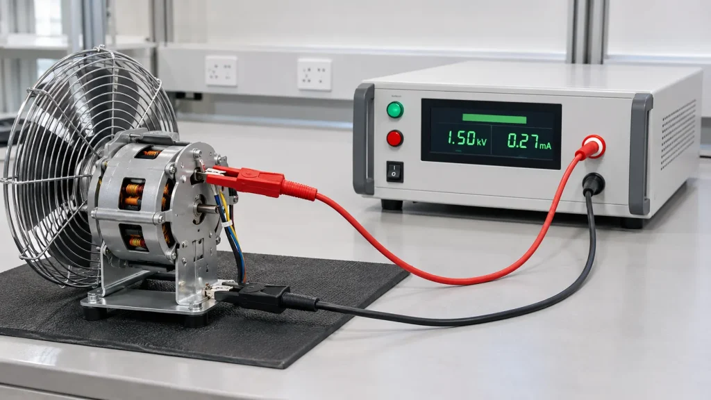
| Dielectric Strength Tester | Performs the applicable post-test electric strength assessment under Clause 19.13 and 16.3. |
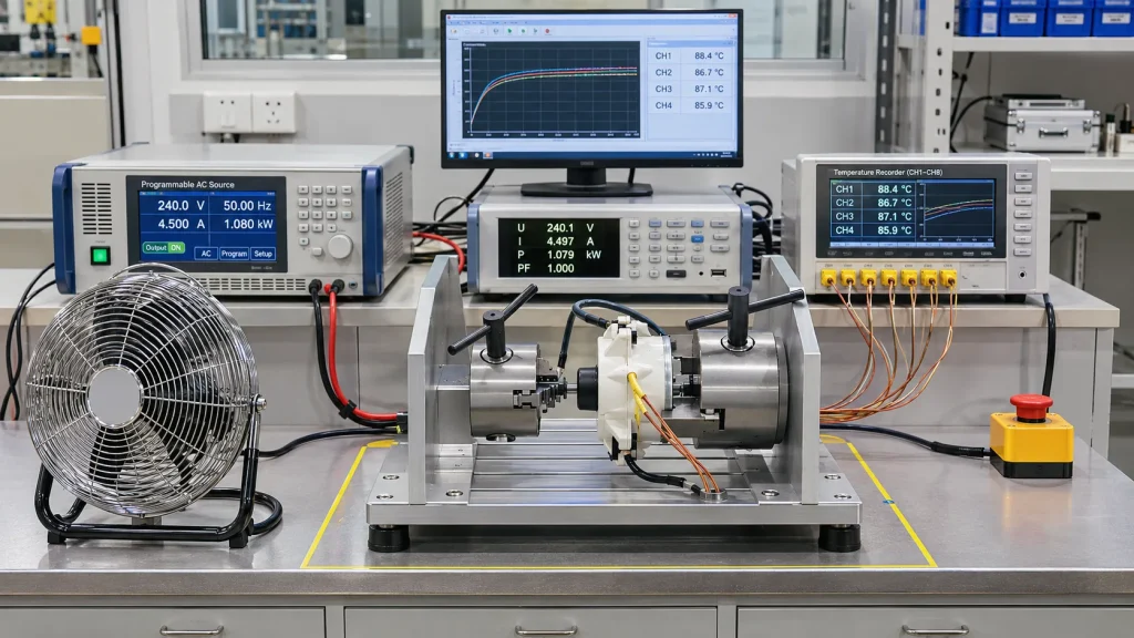
The exact equipment configuration depends on the appliance, motor type, test duration and laboratory procedure. In particular, the mechanical fixture must be designed around the actual motor shaft, rotor arrangement or driven component.
For winding temperature assessment, IEC 60335-1 Clause 11.3 generally specifies the resistance method. Thermocouples are used when the winding is non-uniform or when making the necessary electrical connections for resistance measurement is difficult. A multi-channel temperature recorder is useful for continuous monitoring, but it should not automatically be treated as a replacement for the specified winding resistance method.
Where thermocouples are used, their locations should be selected to identify the relevant hot spots while minimizing disturbance to the component under test.
How Is the Locked-Rotor Test Performed?
The test sequence should be established from the appliance design, circuit diagram and applicable standard edition. The following workflow provides a practical overview of the main laboratory activities.
Sample Inspection and Measurement Preparation
Before energizing the appliance, review the motor specifications, wiring diagram, rated voltage, rated frequency, capacitor arrangement and protective components.
Identify the relevant winding measurement points and other components that may experience significant temperature increases. Confirm that the measurement instruments, recording channels and connections are functioning correctly.
Mechanical Locking and Sample Positioning
Position the appliance in the required operating orientation and secure it against unintended movement. Lock the rotor or relevant moving parts according to the applicable test method.
The fixture should provide sufficient mechanical restraint while avoiding unnecessary changes to the appliance’s construction, enclosure or heat dissipation characteristics.
Capacitor Open-Circuit and Short-Circuit Conditions
Special consideration is required for appliances incorporating motors with capacitors in the auxiliary winding circuit.
Under Clause 19.7, the rotor is locked and the capacitors are open-circuited one at a time. The test is then repeated with the capacitors short-circuited one at a time, except for capacitors classified as S2 or S3 under the referenced IEC 60252-1 requirements.
These conditions simulate different electrical fault scenarios that may affect motor starting, current consumption and winding temperature. The test configuration should be based on the actual motor circuit rather than applying capacitor faults indiscriminately to every appliance.
Rated-Voltage Operation and Test Duration
For each applicable test condition, the appliance is supplied at rated voltage. The required duration is determined by the control arrangement and operating category specified in Clause 19.7.
| Appliance Condition | Test Duration |
|---|---|
| Appliances provided with a timer or programmer | Maximum period allowed by the timer or programmer |
| Hand-held appliances, appliances kept switched on by hand or foot, and appliances continuously loaded by hand | 30 seconds |
| Other appliances operated while attended | 5 minutes |
| Other appliances | Until steady conditions are established |
Important: The relevant Part 2 standard identifies appliances for which the 5-minute test applies. The duration should not be assigned solely according to an informal classification of the appliance or its intended operating environment.
Continuous Temperature and Electrical Monitoring
During operation, record the relevant winding temperature and monitor the electrical operating parameters. Observe the response of thermal protectors and other protective components, where fitted.
For tests continued until steady conditions are established, the temperature development and protective device operation should be documented throughout the test period.
Evaluating Motor Winding Temperature Under Table 8
Winding temperature is one of the principal evaluation parameters in the locked-rotor test. IEC 60335-1 Clause 19.7 requires the winding temperature not to exceed the applicable limits specified in Table 8.
An important distinction is that Table 8 specifies maximum winding temperatures in degrees Celsius (°C), not temperature rises in kelvin (K). The applicable limit depends on the winding insulation class and the operating category of the appliance.
| Operating Category | 105 (A) | 120 (E) | 130 (B) | 155 (F) | 180 (H) | 200 (N) | 220 (R) | 250 |
|---|---|---|---|---|---|---|---|---|
| Not operated until steady conditions | 200 | 215 | 225 | 240 | 260 | 280 | 300 | 330 |
| Steady conditions – impedance protected | 150 | 165 | 175 | 190 | 210 | 230 | 250 | 280 |
| Protective device – first hour maximum | 200 | 215 | 225 | 240 | 260 | 280 | 300 | 330 |
| Protective device – after first hour maximum | 175 | 190 | 200 | 215 | 235 | 255 | 275 | 305 |
| Protective device – after first hour arithmetic average | 150 | 165 | 175 | 190 | 210 | 230 | 250 | 280 |
Values are maximum winding temperatures in °C, reproduced from the operating categories in IEC 60335-1 Table 8. The correct row must be selected according to the appliance protection arrangement and whether steady conditions are established.
For appliances operating until steady conditions are established, the distinction between impedance protection and protection by a protective device is particularly important. Where a protective device is used, Table 8 specifies separate limits for the first hour and the period after the first hour, including an arithmetic average temperature requirement.
Temperature measurement should therefore be planned before testing begins. Where the resistance method is applicable, winding resistance measurements are used to determine the winding temperature. Thermocouples may be appropriate when the conditions described in Clause 11.3 are met.
Using only a surface temperature reading or an external motor casing temperature as a substitute for the required winding temperature assessment may lead to an incomplete evaluation.
Post-Test Electrical Strength and Safety Assessment
Passing the winding temperature assessment alone does not establish compliance with the abnormal operation requirements. The final evaluation must also consider Clause 19.13 and the applicable electrical safety requirements.
During the test, the appliance must not emit flames, molten metal or poisonous or ignitable gas in hazardous amounts. Applicable temperature-rise limits in Table 9 must also be respected.
After the test, when the appliance has cooled to approximately room temperature, the following assessments are relevant:
- Protection against electric shock: Compliance with Clause 8 must not be impaired.
- Electric strength: Applicable insulation, other than the specified Class III exceptions, must withstand the electric strength test of Clause 16.3, using the test voltage specified in Table 4.
- Functional insulation: Where a control operates or is interrupted, the relevant clearances and creepage distances across functional insulation must withstand the specified electric strength assessment at twice the working voltage.
- Mechanical and operational safety: If the appliance remains operable, it must comply with the applicable requirements of Clause 20.2.
- Protective circuit integrity: The appliance must not undergo a dangerous malfunction, and protective electronic circuits must not fail if the appliance remains operable.
Clause 19.13 also specifies the relevant conditions for insulation cooling and the electric strength test. The humidity treatment of Clause 15.3 is not applied before this post-test electric strength assessment. Appliances normally immersed in or filled with conducting liquid have an additional water immersion conditioning requirement before the test.
For laboratories performing these assessments, appropriate electrical safety testing equipment is an important part of the overall test capability.
Common Challenges in Locked-Rotor Testing
Although the principle of a locked-rotor test appears straightforward, several practical details can influence the reliability and interpretation of the results.
Selecting the Correct Locking Method
Locking the wrong component or applying an unsuitable fixture can change the mechanical conditions of the test. The laboratory should first determine whether the motor rotor or another moving part must be locked under Clause 19.7.
Identifying the Actual Winding Hot Spot
Temperature measurements taken at unsuitable locations may not represent the winding temperature accurately. The measurement method and sensor location should be selected according to the winding construction and the requirements of Clause 11.3.
Handling Capacitor Fault Conditions Correctly
Capacitors in auxiliary winding circuits require specific open-circuit and short-circuit test conditions. The relevant capacitor classification and any applicable exception must be verified before the test plan is finalized.
Choosing the Correct Test Duration and Temperature Limits
The 30-second, 5-minute and steady-condition test categories are not interchangeable. Laboratories must also distinguish between the different Table 8 limits for impedance-protected motors and motors protected by protective devices.
Considering the Applicable Part 2 Standard
A general Part 1 test procedure should not be used without checking the relevant appliance-specific standard. Product-specific requirements may modify the test conditions or introduce additional assessments.
Selecting Equipment for Reliable Motor Abnormal Operation Testing
A practical locked-rotor test system should be configured around the appliance’s motor characteristics, mechanical structure, electrical ratings and required measurement parameters.
Depending on the application, a laboratory setup may integrate:
- AC power supply with suitable rated voltage, frequency and current capacity.
- Multi-channel temperature acquisition and thermocouple monitoring.
- Winding resistance measurement for applicable temperature determination.
- Voltage, current and power monitoring instruments.
- Application-specific rotor locking fixtures or moving-part restraint mechanisms.
- Dielectric strength testing equipment for post-test electrical safety evaluation.
There is no single universal fixture configuration suitable for every motor-operated appliance. Mechanical locking arrangements, sensor placement, measurement channels and operating conditions should be determined from the actual sample and applicable test requirements.
KINGPO develops electrical safety testing equipment, specialized fixtures and integrated laboratory testing solutions for household appliance and related product evaluations. Its engineering approach combines test-method analysis, mechanical fixture design, electrical measurement, software and system integration according to the requirements of individual applications.
For laboratories planning a new motor abnormal operation test capability, KINGPO can discuss the required configuration based on the applicable standard edition, motor type, rated electrical parameters, sample structure and intended test scope.
Discuss Your Motor Testing Requirements with KINGPO
Whether you are establishing a new laboratory test setup or upgrading existing motor safety testing capabilities, our engineering team can help review the test requirements and discuss a suitable equipment configuration.
Frequently Asked Questions
Is the IEC 60335-1 Clause 19.7 test only applicable to single-phase induction motors?
No. Clause 19.7 is not limited to single-phase induction motors. Its application depends on the appliance construction and motor operating characteristics. Other motor types may also be subject to different abnormal operation requirements, such as the series motor test in Clause 19.10.
Are all motor capacitors required to undergo open-circuit and short-circuit testing?
The specific requirements apply to motors having capacitors in the auxiliary winding circuit. Capacitors are open-circuited one at a time, and the test is repeated with capacitors short-circuited one at a time, subject to the stated exception for S2 and S3 capacitor classes under the referenced IEC 60252-1 requirements.
Does Table 8 specify winding temperature rise or maximum winding temperature?
Table 8 specifies maximum winding temperature in degrees Celsius (°C), not temperature rise in kelvin (K). The applicable limit depends on the winding insulation class and the operating category of the appliance.
Can thermocouples be used for winding temperature measurement?
Yes, where the conditions in Clause 11.3 permit their use. The standard generally specifies the resistance method for winding temperature determination, with thermocouples used when the winding is non-uniform or the necessary electrical connections are difficult to make.
Is the 5-minute test duration applicable to every attended appliance?
No. Clause 19.7 specifies 5 minutes for other appliances operated while attended, and its note states that appliances subject to this duration are indicated in the relevant Part 2 standard. The applicable product-specific requirements must be checked.
Is passing the winding temperature limit sufficient to pass the test?
No. The appliance must also satisfy the applicable requirements of Clause 19.13, including protection against electric shock, electric strength after cooling, temperature-rise limits and the absence of dangerous malfunction.
Standards Reference
IEC 60335-1:2020, Edition 6.0, including applicable amendments and corrections. The IEC Webstore lists the consolidated publication IEC 60335-1:2020 + AMD1:2025 CSV.
Relevant clauses discussed: 11.3, 16.3, 19.7, 19.10 and 19.13.
For EN adoption and national implementation, confirm the applicable edition, amendments and relevant Part 2 requirements for the target market. This article is a technical overview and does not replace the official standard or a conformity assessment.