
IEC 61010-1 Laboratory Safety Testing Overview
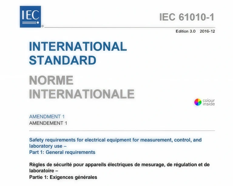
This IEC 61010-1 equipment guide is intended for test engineers, laboratory planners, certification teams and manufacturers evaluating electrical equipment for measurement, control and laboratory use. It organizes the applicable test functions into shared measuring instruments, standard-specific fixtures, measuring networks, conditioning equipment and specialized test systems.
The clause checklist is based on the uploaded IECEE OD-5003-F1 2025 Template Equipment List for IEC 61010-1:2010/AMD1:2016. The final column maps each test function to available KingPo equipment or to a practical configuration description where a dedicated product page is not yet required.
This page is an equipment-selection and website-navigation guide. It does not reproduce or replace IEC 61010-1 or IECEE documentation. Test conditions, limits, classifications and final compliance decisions should be confirmed from the official standard and the responsible certification body.
Standard Information
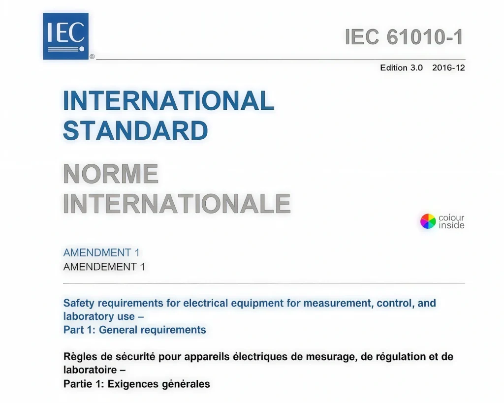
| Standard | IEC 61010-1:2010/AMD1:2016 |
| Title | Safety requirements for electrical equipment for measurement, control, and laboratory use — Part 1: General requirements |
| Document Basis | IECEE OD-5003-F1 2025, Template Equipment List, Ed.1.4 |
| Equipment List Status | Provisional in the uploaded IECEE equipment list |
| Product Scope | Electrical equipment for measurement, control and laboratory use |
| Testing Focus | Electrical shock and energy hazards, access protection, insulation, mechanical strength, heating, fire, IP protection, radiation, pressure/leakage and environmental conditioning |
| IECEE Equipment Classification | R = Required; S = May be subcontracted; W = May be witnessed at a CTF, another CBTL or an outside subcontractor; 3PPS = Three Phase Power Supply required. |
| Page Purpose | Clause-based equipment selection, laboratory gap analysis and internal product mapping for IEC 61010-1 safety testing. |
IEC 61010-1 Testing and Measuring Equipment Checklist
The table below retains the complete set of clause and annex entries from the uploaded IECEE equipment list. The Recommended KingPo Equipment column links only to relevant existing pages; unconfirmed or standard-specific items remain as plain equipment descriptions to avoid inaccurate cross-standard mapping.
| Clause | Measurement / Testing | Testing / Measuring Equipment or Material Needed | Recommended KingPo Equipment |
|---|---|---|---|
| 4.3.1 | Temperature / humidity / air pressure | Temperature indicator / recorder; humidity indicator / recorder; air-pressure indicator / recorder. | Temperature indicator / recorder; humidity indicator / recorder; air-pressure indicator / recorder. |
| 4.3.2.5 / 5.1.3 | Input voltage / current / power / frequency | Suitable voltmeter; current / power meter; frequency measuring device. | Suitable voltmeter; current / power meter; frequency measuring device. |
| 4.4.2.7.2 / 4.4.2.7.3 | Short circuit / overload | Multimeter; current meter; power meter; temperature recorder with thermocouples or suitable resistance-measuring device; suitable variable resistor(s); stopwatch. | Multimeter; current meter; power meter; temperature recorder with thermocouples or suitable resistance-measuring device; suitable variable resistor(s); stopwatch. |
| 4.4.4.2 / 10.4 | Temperature measurements | Temperature recorder with thermocouple. | Temperature recorder with thermocouple. |
| 4.4.4.3 | Spread of fire | White tissue paper; soft wood; cheesecloth. | White tissue paper; soft wood; cheesecloth. |
| 5.3 | Durability of markings | Cloth; specified agent or 70% isopropyl alcohol; suitable timer / stopwatch. | Cloth; specified agent or 70% isopropyl alcohol; suitable timer / stopwatch. |
| 6.1.1 / 6.3 / 6.10.3 | Residual energy | Suitable oscilloscope recorder / setup; RCL meter; length-measurement scale. | KP-1060 Plug Capacitor Discharge Tester |
| 6.2 | Accessibility | Test fingers as per Annex B with suitable means to evaluate application force; 100 mm long test pin (Ø4 mm); Ø3 mm test pin; force gauge. | IEC 61032 Test Probes |
| 6.3.1 / 6.3.2 | Accessible voltage / current / capacitance / stored energy | Measuring circuits / filter networks of Annex A; multimeters; RCL meter; oscilloscope; timer. | Leakage Current Box 3 in 1 IEC 61010-1 Leakage Current Tester |
| 6.5.2.3 / 6.5.2.4 / 6.5.2.5 / 6.5.2.6 / 6.5.4 | Bonding impedance / earth continuity | Current source; multimeter; current meter; timer; torque gauge for screw assemblies; caliper. | Current source; multimeter; current meter; timer; torque gauge for screw assemblies; caliper. |
| 6.6.2 / 6.10.3 | External-circuit terminals — capacitive discharge | Multimeter; oscilloscope; suitable probe (100 MΩ input impedance, max. input capacitance 25 pF); isolation transformer; suitable switch-off unit; timer; Annex A measuring circuits / filter networks. | KP-1060 Plug Capacitor Discharge Tester |
| 6.7 / 10.5.1 | Clearance and creepage distances | Micrometer / caliper; force gauge; multimeter; oven. | Micrometer / caliper; force gauge; multimeter; oven. |
| 6.7.1.3 | Tracking index | CTI tester; Test Solution A. | IEC 60112 Comparative Tracking Index Tester |
| 6.8.1 | Distances between terminal and foil | Length-measurement scale. | Length-measurement scale. |
| 6.8.2 | Humidity conditioning | Humidity chamber: 25–40 °C, RH up to 96%; chronometer. | Temperature and Humidity Chamber |
| 6.8.3 | Dielectric strength tests | High-voltage AC / DC tester or impulse tester. | High-voltage AC / DC tester or impulse tester. |
| 6.10.2.1 | Cord entry test | Micrometer / caliper. | Micrometer / caliper. |
| 6.10.2.2 | Cord anchorage test | Suitable force gauge; torque gauge. | Cord Anchorage Torque Tester |
| 7.3.4 | Limitation of force and pressure | Force gauge. | Force gauge. |
| 7.3.5 | Gap limitations between moving parts | Length-measurement scale. | Length-measurement scale. |
| 7.4 | Stability tests | Tape measure; suitable weight scale; force gauge; length-measurement scale; torque gauge; 10° inclinometer [0–45°]. | Stability Inclined Plane Test Equipment |
| 7.5 | Strength of handles | Weight scale; timer; weights; 70 mm wide strap; length-measurement scale. | KP-HD38-1 70 mm Strap Tester |
| 7.6 | Wall mounting | Timer; weight scale; weights; length-measurement scale. | Timer; weight scale; weights; length-measurement scale. |
| 8.2.1 | Static test | 12 mm diameter hemispherical-end rod; force gauge; oven; timer; high-voltage AC / DC tester or impulse tester. | 12 mm diameter hemispherical-end rod; force gauge; oven; timer; high-voltage AC / DC tester or impulse tester. |
| 8.2.2 | Dynamic test | Ø50 mm hardened steel ball, 500 g, as specified. | Ø50 mm hardened steel ball, 500 g, as specified. |
| 8.3.1 | Drop test | Weight scale; length-measurement scale; 30° inclinometer; smooth hard rigid surface; 10 mm and 20 mm wooden studs. | Weight scale; length-measurement scale; 30° inclinometer; smooth hard rigid surface; 10 mm and 20 mm wooden studs. |
| 8.3.2 | Hand-held equipment | 50 mm thick hardwood, density >700 kg/m³; length-measurement scale; climatic chamber; timer. | Temperature and Humidity Chamber |
| 9.3.1 / 14.7 | Flammability tests | Bunsen burner; gas; oven. | Bunsen burner; gas; oven. |
| 9.3.2 | Constructional requirements | Inclinometer; length-measurement scale; caliper. | Inclinometer; length-measurement scale; caliper. |
| 9.4 | Limited energy circuits | Multimeters; current meter; suitable variable resistors; stopwatch. | Multimeters; current meter; suitable variable resistors; stopwatch. |
| 10.4.2 | Heating equipment | Test corner; black plywood, 20 mm thick. | Test corner; black plywood, 20 mm thick. |
| 10.4.3 | Heating equipment — fixed installation | Black plywood walls, 10 mm thick. | Black plywood walls, 10 mm thick. |
| 10.5.2 | Enclosures | Oven 200 °C; temperature recorder with thermocouple; chronometer. | Oven 200 °C; temperature recorder with thermocouple; chronometer. |
| 10.5.3 (1) | Insulating materials — ball pressure | Ball-pressure apparatus with suitable means to evaluate application force; heating cabinet. | IEC 60695-10-2 Ball Pressure Test Apparatus |
| 10.5.3 (2) | Insulating materials — Vicat | Vicat ISO 306 Method A setup: heating chamber, heat-transfer liquid, weight, penetration indicator, needle, temperature recorder, caliper, dielectric tester. | Vicat Test Equipment |
| 11.2 | Cleaning / decontamination | As per manufacturer’s instructions. | As per manufacturer’s instructions. |
| 11.3 | Spillage | Water; 0.2 litre measure; tape; timer / stopwatch; length-measurement scale. | Water; 0.2 litre measure; tape; timer / stopwatch; length-measurement scale. |
| 11.4 (6.8.4) | Overflow | Water or appropriate fluid; volume indicator; inclinometer; high-voltage AC / DC tester or impulse tester; timer / stopwatch. | Water or appropriate fluid; volume indicator; inclinometer; high-voltage AC / DC tester or impulse tester; timer / stopwatch. |
| 11.6 | Specially protected equipment (IP rated) | Test equipment according to IEC 60529. | IEC 60529 IPX1–IPX8 Waterproof Test Chamber |
| 11.7 | Fluid pressure and leakage | Suitable pressure and volume measurement devices. | Suitable pressure and volume measurement devices. |
| 12.2.1 | Ionizing radiation | Suitable ionization meter; indicative limit 5 µSv/h. | Suitable ionization meter; indicative limit 5 µSv/h. |
| 12.3 | UV radiation | UV meter; compliance / limit according to the referenced guidance. | UV meter; compliance / limit according to the referenced guidance. |
| 12.4 | Microwave radiation | Suitable measuring device. | Suitable measuring device. |
| 12.5.1 | Sound pressure level | Sound level meter. | Sound level meter. |
| 12.5.2 | Ultrasonic pressure | Suitable indicator / ultrasonic level meter. | Suitable indicator / ultrasonic level meter. |
| 12.6 | Laser sources | Test equipment according to IEC 60825-1. | IEC 60825-1 Laser Testing Equipment |
| 13.2.3 | High vacuum devices | Test equipment according to IEC 60065. | Test equipment according to IEC 60065. |
| 14.2 | Motors | Temperature recorder with thermocouple; multimeter. | Temperature recorder with thermocouple; multimeter. |
| 14.3 | Over-temperature protection devices | Multimeters; oscilloscope; temperature recorder with thermocouple; high-voltage AC / DC tester or impulse tester. | Multimeters; oscilloscope; temperature recorder with thermocouple; high-voltage AC / DC tester or impulse tester. |
| 14.6 | Mains transformers tested outside equipment | Measuring equipment referenced from 4.4.2.7.2 / 4.4.2.7.3. | Measuring equipment referenced from 4.4.2.7.2 / 4.4.2.7.3. |
| 14.8 | Transient overvoltage | Impulse tester to IEC 61180-1. | Impulse tester to IEC 61180-1. |
| 15.3 | Reliability — interlocks | Multimeters. | Multimeters. |
| Annex A | Measurement circuits | Measurement circuits A.1 to A.4. | IEC 60990 Touch Current and Protective Conductor Current Measuring Network |
| Annex B | Standard test fingers | Test Probe 11 of IEC 61032; Test Probe B of IEC 61032. | IEC 61032 Test Probe 11 and Test Probe B |
| Annex H | Qualification of conformal coating for protection against pollution | Climatic chamber; chronometer. | Temperature and Humidity Chamber |
| Annex K | Insulation requirements not covered by 6.7 | Suitable measuring equipment as noted for 6.7. | Suitable measuring equipment as noted for 6.7. |
| General | Three-phase power supply | Three-phase variac; three-phase power meter. | Three-phase variac; three-phase power meter. |
Scope note: the IECEE list classifies tracking index, flammability, Vicat, fluid pressure/leakage, radiation-related measurements, high-vacuum testing and Annex H conditioning as subcontractable (S) entries; IP testing and the general three-phase supply entry are shown as witnessed (W) entries. Confirm the intended in-house laboratory scope before purchasing specialized equipment.
Laboratory Configuration and Equipment Consolidation
A 57-row equipment list does not mean 57 independent instruments. IEC 61010-1 repeatedly uses the same electrical, mechanical and environmental instruments across several clauses. A practical laboratory BOM should consolidate shared instruments first, then add clause-specific fixtures and specialized systems.
| Equipment Layer | Typical Equipment | Engineering Selection Point |
|---|---|---|
| Shared electrical instruments | Multimeter, current/power meter, oscilloscope, RCL meter, current source, high-voltage / impulse tester | Select against the most demanding voltage, current, bandwidth, input impedance, waveform and source requirement among the applicable clauses. |
| Shared mechanical instruments | Force gauge, torque gauge, caliper, micrometer, weight scale, inclinometer and length scale | Check range, resolution, loading direction, attachment geometry and calibration points before consolidating equipment. |
| Shared conditioning equipment | Oven, humidity chamber, climatic chamber, temperature recorder and thermocouples | Confirm chamber volume, temperature/RH range, uniformity, sample loading and whether fixtures remain installed during conditioning. |
| Standard-specific fixtures and networks | Annex A measuring circuits, Annex B probes, test pins, static rod, impact ball, 70 mm strap, test corner and spillage accessories | Verify the exact clause, figure, dimensions, applied force/energy and test function rather than selecting by product name alone. |
Representative Shared-Instrument Use Across Clauses
| Instrument | Representative Clauses | Key Check |
|---|---|---|
| Oscilloscope | 6.1.1 / 6.3 / 6.10.3; 6.3.1 / 6.3.2; 6.6.2 / 6.10.3; 14.3 | Bandwidth, probe rating, input impedance/capacitance and transient capture. |
| High-voltage / impulse tester | 6.8.3; 8.2.1; 11.4; 14.3; 14.8 | AC/DC versus impulse requirement, voltage range, waveform, trip level and test timing. |
| Force gauge | 6.2; 6.7 / 10.5.1; 6.10.2.2; 7.3.4; 7.4; 8.2.1 | Force range, resolution, compression/tension direction and fixture interface. |
| Temperature recorder | 4.4.2.7.2 / 4.4.2.7.3; 4.4.4.2 / 10.4; 10.5.2; 14.2; 14.3 | Channel count, thermocouple type, accuracy, isolation and sampling interval. |
| Humidity / climatic chamber | 6.8.2; 8.3.2; Annex H | Temperature/RH range, chamber volume and specimen conditioning arrangement. |
Standard-Specific Fixtures and Measurement Networks
These items are clause- or annex-specific and should be controlled separately from general bench instruments. For quotation and calibration planning, specify the applicable clause/figure together with dimensions, load, frequency range or measurement interface as relevant.
| Clause / Annex | Dedicated Item | Configuration Check |
|---|---|---|
| 6.3.1 / 6.3.2 / Annex A | Measuring Circuits A.1 to A.4 | Confirm the exact Annex A network, frequency range, component values, output terminals and external measuring instrument. |
| 6.2 / Annex B | Test Probe 11, Test Probe B, Ø4 mm × 100 mm test pin and Ø3 mm test pin | Confirm probe figure, dimensions, application force and hazardous-part indication arrangement. |
| 8.2.1 | 12 mm diameter hemispherical-end rod | Confirm rod-end geometry, applied force, dwell time and any post-test dielectric-strength requirement. |
| 8.2.2 | Ø50 mm hardened-steel ball, 500 g | Confirm diameter, mass, hardness and the specified dynamic-test arrangement. |
| 7.5 | 70 mm wide handle-strength strap | Confirm strap width, loading method, weight range and handle geometry. |
| 10.4.2 / 10.4.3 | Black-plywood test corner / fixed-installation walls | Confirm plywood thickness, surface finish, wall geometry and EUT installation arrangement. |
| 11.3 / 11.4 | Spillage and overflow accessory set | Confirm liquid volume, delivery method, inclinometer, timing and post-test dielectric-strength measurement. |
Available KingPo Equipment Mapping
The following existing KingPo equipment can support specific IEC 61010-1 test functions. Where a product is also used under other IEC standards, the final configuration should be checked against the exact IEC 61010-1 clause, range and fixture requirements.
| Product / Group | IEC 61010-1 Use |
|---|---|
| IEC residual-voltage / capacitor-discharge tester | Residual energy and external-terminal capacitive-discharge evaluation |
| IEC 61032 test probes | Clause 6.2 accessibility and Annex B probe requirements |
| Leakage current measuring network | Related accessible-current / touch-current measurement configurations; verify network against the exact IEC 61010-1 Annex A requirement before use |
| Comparative Tracking Index tester | Clause 6.7.1.3 tracking-index evaluation |
| Temperature and humidity chamber | Humidity conditioning and Annex H climatic conditioning |
| Cord anchorage tension and torque tester | Clause 6.10.2.2 cord anchorage — confirm required force and torque range |
| 70 mm strap handle-strength fixture | Clause 7.5 handle-strength loading arrangement — confirm load capacity and fixture geometry |
| Vicat softening-temperature tester | Clause 10.5.3 insulating material Vicat testing per ISO 306 Method A |
| IEC 60529 IPX1–IPX8 water ingress system | Clause 11.6 specially protected / IP-rated equipment |
| Flammability test equipment / Ball pressure test apparatus | Clauses 9.3.1 / 14.7 flammability testing and Clause 10.5.3 ball-pressure evaluation. |
Engineering Configuration Notes
1. Build the laboratory BOM from the intended clause scope
Start from the certification or internal verification scope, not from a generic equipment package. Equipment used only for subcontracted or witnessed tests should not automatically be included in the in-house laboratory BOM.
2. Consolidate repeated instruments before selecting quantities
Multimeters, oscilloscopes, force gauges, ovens, temperature recorders, timers and high-voltage testers recur across multiple clauses. One qualified instrument can normally support several clauses unless simultaneous testing, range limitations or different fixture interfaces require additional units.
3. Control Annex A and Annex B items as standard-specific fixtures
Annex A measurement circuits and Annex B probes should be identified by figure and test function. Do not replace them with a general leakage-current network or accessibility probe solely because the products appear mechanically or electrically similar.
4. Verify multi-standard equipment against IEC 61010-1 conditions
A tester used for IEC 60335, IEC 60601 or IEC 62368 may also be suitable for IEC 61010-1, but the required voltage, force, bandwidth, fixture dimensions, timing, environmental condition and post-test evaluation must match the applicable IEC 61010-1 clause.
5. Treat calibration scope as part of equipment selection
For voltage, current, resistance, force, torque, temperature, humidity, time, dimensions and pressure, define the required measurement range and calibration points during configuration. This avoids purchasing equipment that cannot later support the laboratory’s uncertainty or traceability requirements.
6. Confirm sample size and installation conditions before selecting chambers and mechanical fixtures
Chamber volume, test-corner dimensions, wall-mounting fixtures, drop-test surfaces and stability arrangements depend on the EUT size, mass and installation method. These parameters should be reviewed before quotation rather than treated as universal accessories.
Technical Inquiry and Configuration Support
- Applicable IEC 61010-1 edition and required clauses
- EUT type, intended use, dimensions and weight
- Rated voltage, current, phase, power and frequency
- Protection class, accessible terminals and relevant energy sources
- Required Annex A measuring circuits and Annex B probes
- Mechanical test scope: force, torque, impact, drop, stability or handle testing
- Environmental / IP / pressure / radiation tests to be performed in-house
- Existing laboratory instruments that can be reused
- Calibration, documentation, data recording and automation requirements
FAQ: IEC 61010-1 Laboratory Equipment Configuration
Which instruments can normally be shared across multiple IEC 61010-1 clauses?
Multimeters, oscilloscopes, force gauges, torque gauges, temperature recorders, ovens, timers and high-voltage or impulse testers occur repeatedly in the IECEE equipment list. One instrument can usually serve several clauses when its range, accuracy, bandwidth, source capability and calibration scope cover the most demanding applicable requirement.
How should Annex A Figures A.1 to A.4 be specified when purchasing measuring circuits?
Specify the exact Annex A figure or complete A.1–A.4 set, the applicable clause, frequency range, external measuring instrument and required calibration or component-value verification. A general leakage-current tester should not be treated automatically as a substitute for a specific Annex A network.
Which probes and pins are required for Clause 6.2 accessibility testing?
Clause 6.2 calls for the Annex B test fingers, a 100 mm long Ø4 mm test pin, a Ø3 mm test pin and a force gauge. Annex B also identifies IEC 61032 Test Probe 11 and Test Probe B. The laboratory should control both probe geometry and the required application-force arrangement.
Can the same high-voltage tester be used for dielectric-strength and transient-overvoltage tests?
Not automatically. Clause 6.8.3 may require AC/DC dielectric-strength capability, while Clause 14.8 calls for an impulse tester to IEC 61180-1. Confirm waveform, peak voltage, source characteristics, trip settings and test timing before assigning one instrument to both functions.
When can one climatic chamber be used for Clause 6.8.2, Clause 8.3.2 and Annex H?
A shared chamber is practical when its usable volume, temperature and humidity ranges, uniformity, stability and specimen arrangement meet each test condition. The environmental profiles and sample fixtures should be checked separately even when the same chamber hardware is used.
How should the R, S and W classifications affect the laboratory equipment BOM?
R entries are required capabilities when the associated clause is included in the laboratory scope. S entries may be subcontracted and W entries may be handled through a witnessed arrangement. Specialized radiation, material, pressure or IP equipment should therefore be purchased only when the laboratory intends to perform those tests in-house.
How can an existing safety laboratory identify only the missing IEC 61010-1 equipment?
Map existing instruments to the applicable clauses by function, range and calibration status rather than by the standard printed on the equipment label. Shared instruments are often reusable, while Annex A networks, Annex B probes, specific test pins, impact accessories and IEC 61010-1 mechanical fixtures are more likely to be genuine gaps.
What should be checked before reusing equipment originally supplied for another IEC standard?
Verify the actual dimensions, force or torque range, impact mass, material, voltage range, waveform, timing, bandwidth and fixture interface against the IEC 61010-1 clause. Similar equipment names do not by themselves establish that the same configuration is technically suitable.
How should the mechanical test equipment for Clauses 7 and 8 be configured?
Provide the EUT dimensions, mass, mounting arrangement and applicable clauses. Then confirm required force, torque, incline angle, impact mass, drop arrangement, surface material and any post-test electrical evaluation. This determines whether a standard accessory is sufficient or a dedicated mechanical test frame is required.
Are spillage, overflow, IP and fluid-pressure tests interchangeable?
No. Spillage and overflow use controlled liquid delivery and post-conditioning checks; IP testing refers to IEC 60529 methods; fluid-pressure and leakage testing requires suitable pressure and volume measurement for the EUT fluid circuit. These should remain separate equipment functions in the laboratory plan.
What should be included in the calibration and verification plan?
Identify all measured quantities used by the laboratory—voltage, current, resistance, capacitance, force, torque, temperature, humidity, time, dimensions, pressure, volume or radiation level—and define calibration points around the actual IEC 61010-1 test ranges. Standard fixtures may also require dimensional or component-value verification.
What information should be sent with an IEC 61010-1 equipment RFQ?
Provide the standard edition, EUT type, dimensions and mass, rated voltage/current/power, phase and frequency, required clauses, intended in-house scope, existing instruments, Annex A/B requirements, environmental or IP requirements and calibration/documentation expectations. Product drawings are useful for customized mechanical, pressure or mounting fixtures.
Need an IEC 61010-1 Clause-Based Equipment Proposal?
Send the required clauses, EUT details and the equipment already available in your laboratory. The remaining probes, measuring networks, electrical safety systems, mechanical fixtures and environmental equipment can then be mapped into a practical quotation list without unnecessary duplication.
