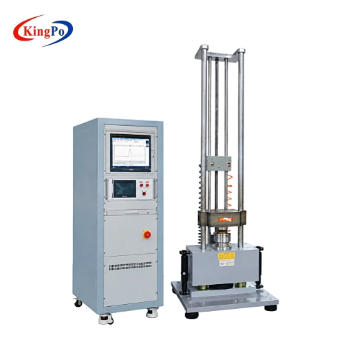
Mechanical shock testing evaluates how a product responds to a rapid acceleration event caused by impact, handling, transportation or operating conditions. Unlike vibration testing, which applies repeated or continuous oscillatory motion, a mechanical shock test subjects the specimen to a short acceleration-time pulse with defined peak acceleration, duration and waveform.
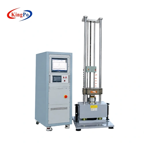
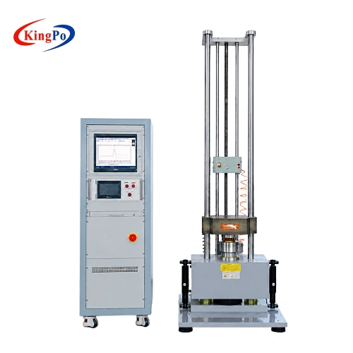
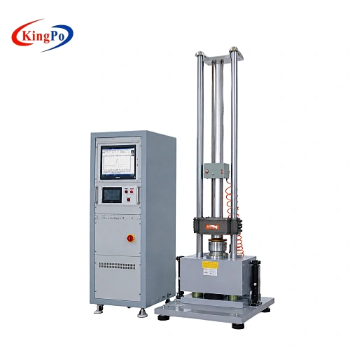
The HSKT10 uses a free-drop mechanical shock system with hydraulic lifting. The DUT is secured to the shock table using a suitable fixture, and the system generates the required shock pulse through the selected waveform-generation arrangement.
An acceleration sensor and shock measurement system capture the actual acceleration-time waveform during the test. This allows the laboratory to evaluate whether the generated pulse corresponds to the required test condition before assessing the DUT for mechanical damage, functional degradation or other acceptance criteria defined by the applicable specification.
The HSKT10 is therefore a shock generation and measurement system rather than a simple drop or impact apparatus.
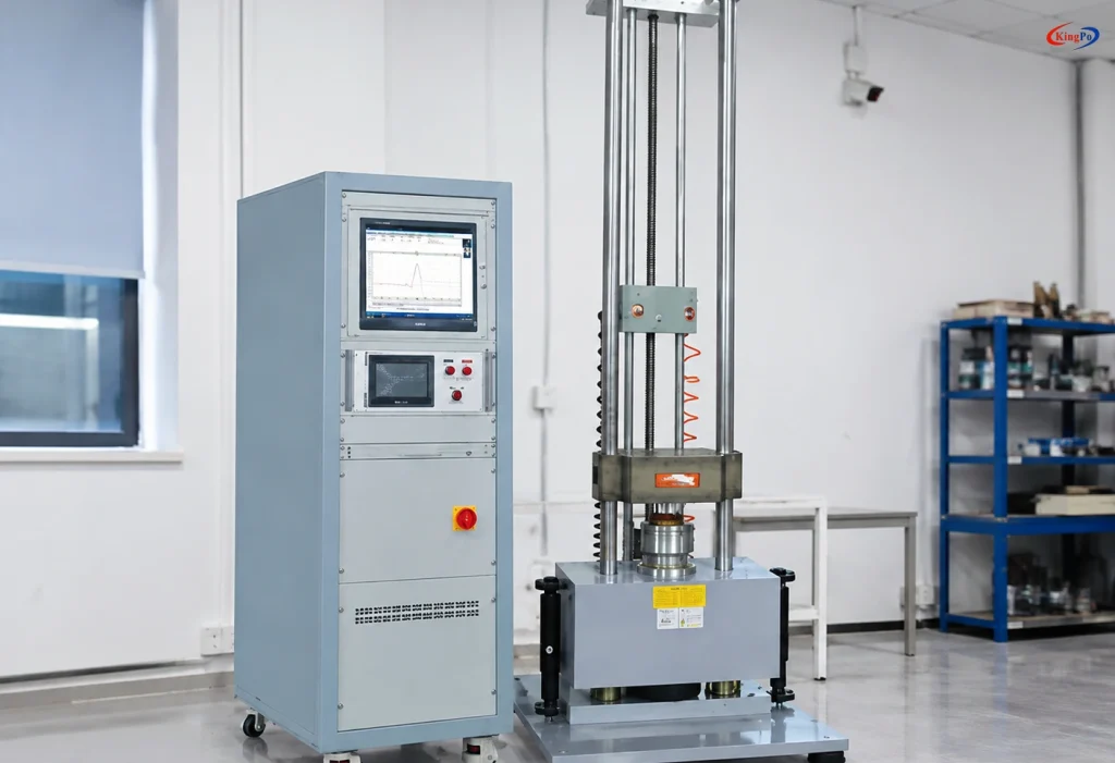
What Does the HSKT10 Test?
The HSKT10 evaluates the ability of a mounted DUT to withstand a defined mechanical shock exposure.
The test focuses on the response of the product to an acceleration pulse rather than on impact energy alone. Depending on the applicable product standard or laboratory procedure, the DUT may be checked for:
- structural damage or deformation;
- loosening or displacement of components;
- cracking or mechanical failure;
- interruption of electrical function;
- change in performance after shock exposure;
- accumulated damage after repeated shocks;
- compliance with a specified acceleration-time shock profile.
The HSKT10 generates and measures the required mechanical input. The final pass/fail criteria are determined by the applicable product standard or customer test specification.
Technical Specifications
Mechanical Shock System
| Parameter | Specification |
|---|---|
| Model | HSKT10 |
| Operating Platform | 200 × 200 mm |
| Maximum Specified Load | 10 kg |
| Peak Acceleration | 20–1500 G |
| Pulse Duration | 0.5–11 ms |
| Shock Principle | Free-drop mechanical shock |
| Lifting System | Hydraulic lifting |
| Equipment Dimensions | 560 × 670 × 2390 mm |
| Equipment Weight | Approx. 650 kg |
| Power Supply | 220 VAC ±10%, 50 Hz |
| Required Electrical Capacity | 2 kVA |
Shock Measurement System
| Parameter | Specification |
|---|---|
| Input Channels | 2 channels |
| Sampling Frequency | 192 kHz |
| Communication Interface | USB 2.0 |
| Measurement Object | Acceleration-time shock waveform |
| Main Functions | Shock waveform acquisition, storage and analysis |
| Control Computer | Included in the original system configuration |
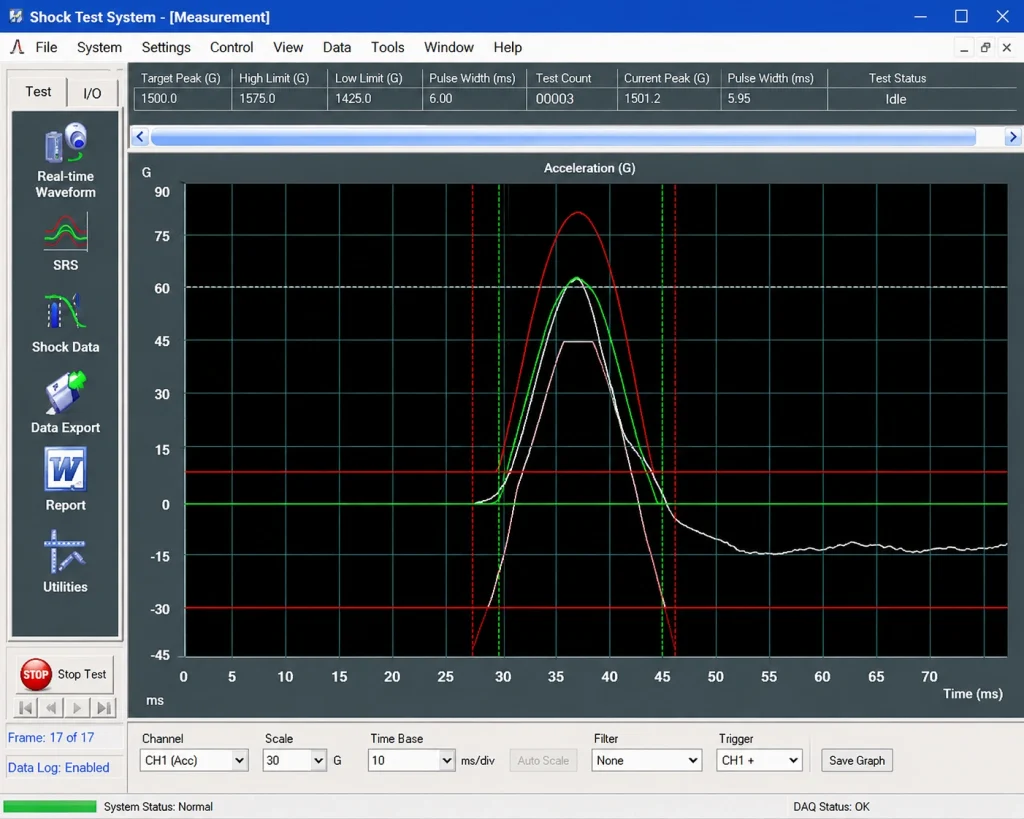
The original HSKT10 technical documentation also describes waveform analysis and shock response spectrum functions. Where SRS or other specific analysis functions are required, the applicable software configuration should be confirmed before quotation.
Acceleration Sensor
| Parameter | Specification |
|---|---|
| Sensor Brand | LAB |
| Sensor Model | 23108 |
| Output Type | Charge type |
| Sensitivity | 3.93 pC/g |
| Frequency Range | 0.5–12 kHz |
| Acceleration Range | ±2500 G |
| Operating Temperature | -40°C to +160°C |
Sensor model and measurement configuration may be reviewed if the project requires specific calibration points, measurement bandwidth or traceability documentation.
Mechanical Shock Test Principle
A mechanical shock test is defined mainly by four parameters:
peak acceleration, pulse duration, waveform and number of shocks.
A typical HSKT10 test procedure is as follows:
- The applicable standard or customer test profile is identified.
- The DUT is mounted to the shock table using a suitable fixture.
- The required acceleration, pulse duration and waveform are configured.
- The mechanical shock system generates the specified transient pulse.
- The acceleration sensor measures the actual acceleration-time response.
- The captured waveform is compared with the required shock profile.
- The DUT is inspected or functionally evaluated according to the applicable acceptance criteria.
The fixture and mounting method are important because the DUT must be mechanically coupled to the shock table without introducing uncontrolled movement that can affect the measured pulse.
Shock Pulse Configuration
Half-Sine Shock
Half-sine is one of the primary mechanical shock pulse shapes supported by the HSKT-series design.
Different pulse conditions are obtained through the appropriate pulse-shaping configuration. The confirmed HSKT10 main specification covers a 0.5–11 ms pulse-duration range.
If the required test specifies a pulse outside this range, the required acceleration, duration and DUT load should be provided for engineering review.
Final-Peak Sawtooth Shock
The original HSKT technical documentation identifies final-peak sawtooth shock as an available test form when the corresponding waveform-generation arrangement is selected.
The required peak acceleration, pulse duration and waveform tolerance should be specified before the system configuration is finalized.
Trapezoidal Shock
Trapezoidal shock pulses can also be considered with the appropriate waveform-generation configuration.
Because different pulse shapes may require different mechanical pulse-shaping arrangements, the required waveform should be stated clearly during equipment selection.
Shock Generation and Braking System
Hydraulic Lifting
The HSKT10 uses hydraulic lifting to raise the shock mechanism before the test event.
A photoelectric encoder arrangement is used in the original design to monitor lifting position, helping control the mechanical condition before shock generation.
Secondary-Shock Suppression
A mechanical shock test should reproduce the required primary pulse without an uncontrolled secondary impact immediately afterward.
The HSKT10 uses pneumatic-hydraulic boosting together with a strong friction braking mechanism to suppress secondary rebound after the shock event.
This allows the primary measured acceleration pulse to be evaluated without unnecessary interference from repeated mechanical bounce.
Buffer and Isolation Arrangement
The shock system incorporates a base, damping structure and airbag-type buffering arrangement.
Its purpose is to reduce the shock force transmitted from the machine to the laboratory floor. Installation conditions should still be reviewed where other sensitive measurement instruments are installed nearby.
System Configuration
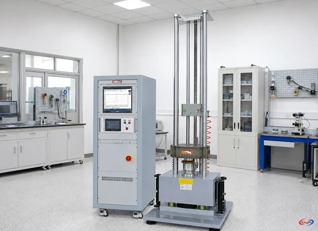
The HSKT10 is supplied as a complete mechanical shock testing system rather than only as a mechanical shock table.
| Equipment | Model / Description | Quantity |
|---|---|---|
| Mechanical Shock Tester | HSKT10 | 1 set |
| Controller | SKC-1 | 1 set |
| Shock Measurement Device | ST-2 | 1 set |
| Acceleration Sensor | LAB | 1 pc |
| Control Computer | Test control and data processing | 1 set |
| Waveform Generator | HB01 | 1 set |
| Safety Device | Audible and visual alarm | 1 set |
| Accessories | Tools, clamps, instructions and related accessories | 1 set |
The final fixture, waveform-generation arrangement and measurement configuration should be selected according to the actual test requirement.
Applicable Standards and Test Scope
IEC 60068-2-27 — Test Ea: Shock
IEC 60068-2-27 defines a general mechanical shock test for determining the ability of a specimen to withstand specified repetitive or non-repetitive shocks.
The relevant product specification determines the required test severity, including acceleration, pulse duration, waveform, number of shocks and test directions.
The HSKT10 can be configured for IEC 60068-2-27 shock testing where the required test profile falls within the capability of the selected system configuration.
It should not be assumed that one acceleration and pulse-duration setting represents all IEC 60068-2-27 applications.
UN 38.3 Test T.4 — Shock
For lithium cell and battery transport testing, UN 38.3 Test T.4 is the mechanical shock test within the UN Manual of Tests and Criteria battery test sequence.
The original HSKT10 documentation identifies UN 38.3 among its supported applications.
For a specific battery project, suitability should be confirmed according to:
- cell or battery type;
- specimen mass;
- required acceleration;
- pulse duration;
- number of shocks;
- test directions;
- fixture and mounting requirements.
The HSKT10 is used for the applicable mechanical shock portion of the test sequence and does not perform the complete set of UN 38.3 tests.
IEC 62133-2 — Clause 7.3.8.2 Shock
IEC 62133-2 specifies safety requirements and tests for portable sealed secondary lithium cells and batteries. Clause 7.3.8.2 addresses mechanical shock testing as part of the standard’s mechanical test requirements.
The HSKT10 can be applied to this shock test where the required acceleration, pulse duration, specimen mass and mounting conditions are within the configured capability of the system. The applicable standard edition and battery configuration should be confirmed for the specific test program.
MIL-STD, GJB and Customer-Specified Shock Profiles
The original HSKT-series documentation references several military and environmental test standards, including MIL-STD and GJB series specifications.
These applications should be treated as profile-dependent mechanical shock testing.
For military, aerospace or customer-specific projects, provide the exact:
- standard number;
- revision or edition;
- method or procedure;
- waveform;
- peak acceleration;
- pulse duration;
- DUT mass and mounting condition.
KINGPO can then review whether the HSKT10 configuration covers the required mechanical shock profile.
Typical Test Objects
The HSKT10 is intended for mounted specimens requiring controlled transient mechanical shock exposure.
Typical DUTs include:
- electronic components;
- electronic modules and assemblies;
- lithium battery cells;
- small battery assemblies;
- automotive electronic components;
- sensors and control modules;
- transportation equipment components;
- aerospace-related components;
- industrial products requiring mechanical shock qualification.
Suitability should always be determined from the required shock profile and mounted load rather than only from the product category.
Mechanical Shock Testing vs. Vibration Testing
Mechanical shock and vibration testing reproduce different mechanical environments.
A mechanical shock tester generates a short-duration transient acceleration event. The principal test parameters are peak acceleration, pulse duration, waveform and the number and direction of shocks.
A vibration test system generates repeated or continuous oscillatory motion over a defined frequency range and may perform sine, sweep or random vibration testing.
Products that require both vibration and mechanical shock qualification may therefore need separate test systems or separate test configurations.
Mechanical Shock Tester vs. Battery Impact Tester
The HSKT10 should not be confused with a conventional battery impact tester.
A battery impact apparatus typically uses a defined impact mass and crossbar to apply a direct physical impact to the battery.
The HSKT10 operates differently. The DUT is mounted to a shock table, and the equipment generates a controlled acceleration-time pulse that is measured using an accelerometer and shock data-acquisition system.
These two test methods reproduce different mechanical conditions and are not interchangeable.
Installation Requirements
| Requirement | Specification |
|---|---|
| Power Supply | 220 V ±10%, 50 Hz |
| Electrical Capacity | 2 kVA |
| Power Arrangement | Independent isolated power supply |
| Compressed Air | 0.5–0.8 MPa |
| Ambient Temperature | Room temperature to 35°C |
| Relative Humidity | 0–85% RH |
| Installation Surface | Flat floor |
| Installation Environment | Low dust and no surrounding corrosive gas |
| Equipment Dimensions | 560 × 670 × 2390 mm |
| Equipment Weight | Approx. 650 kg |
Suitable unloading and handling equipment should be prepared before installation.
Where floor vibration transmission, access dimensions or nearby sensitive laboratory equipment are important, the installation location should be reviewed before shipment.