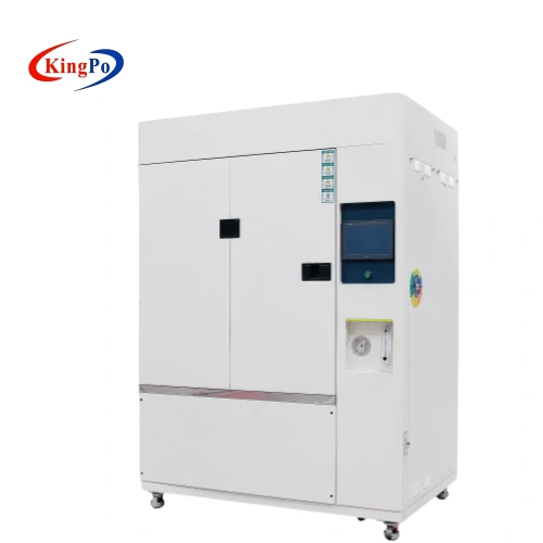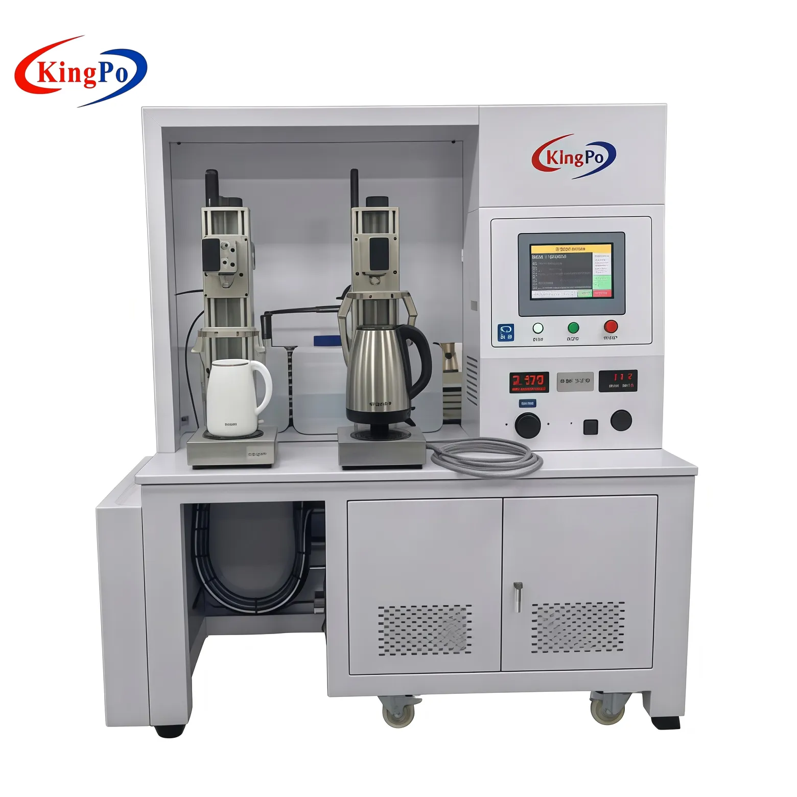
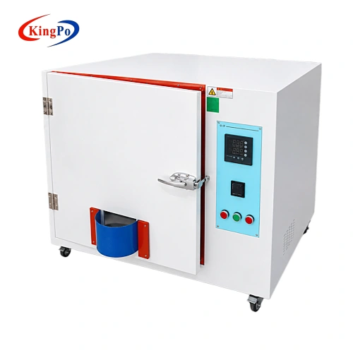
Front view of the Thermally Protected Ballast Heating Test Chamber for IEC 61347-1 Annex D testing
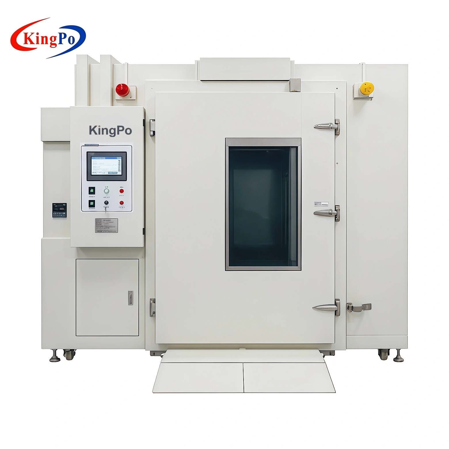
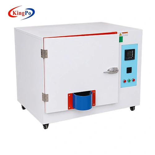
Right-angle view of the Thermally Protected Lamp Controlgear Heating Test Chamber
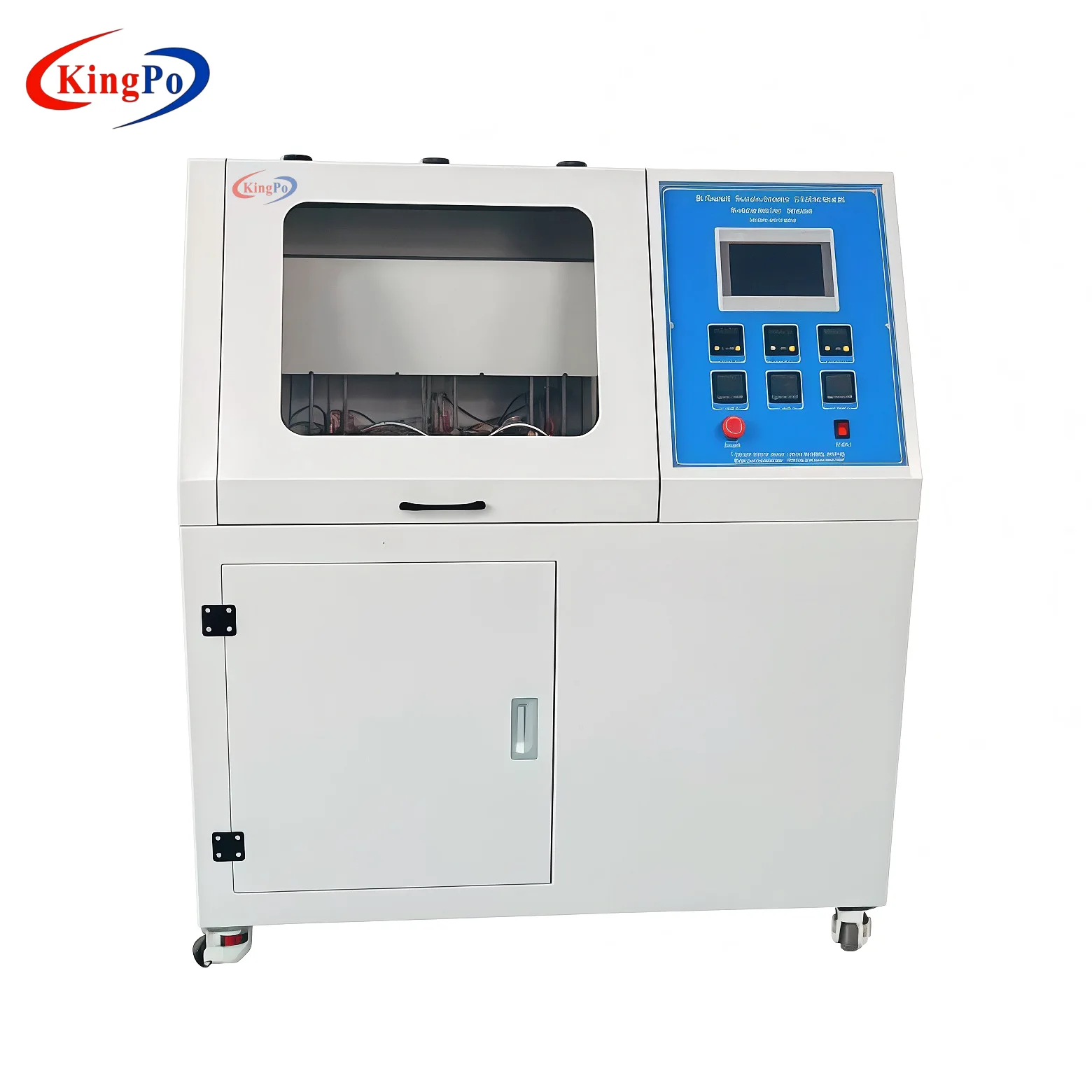
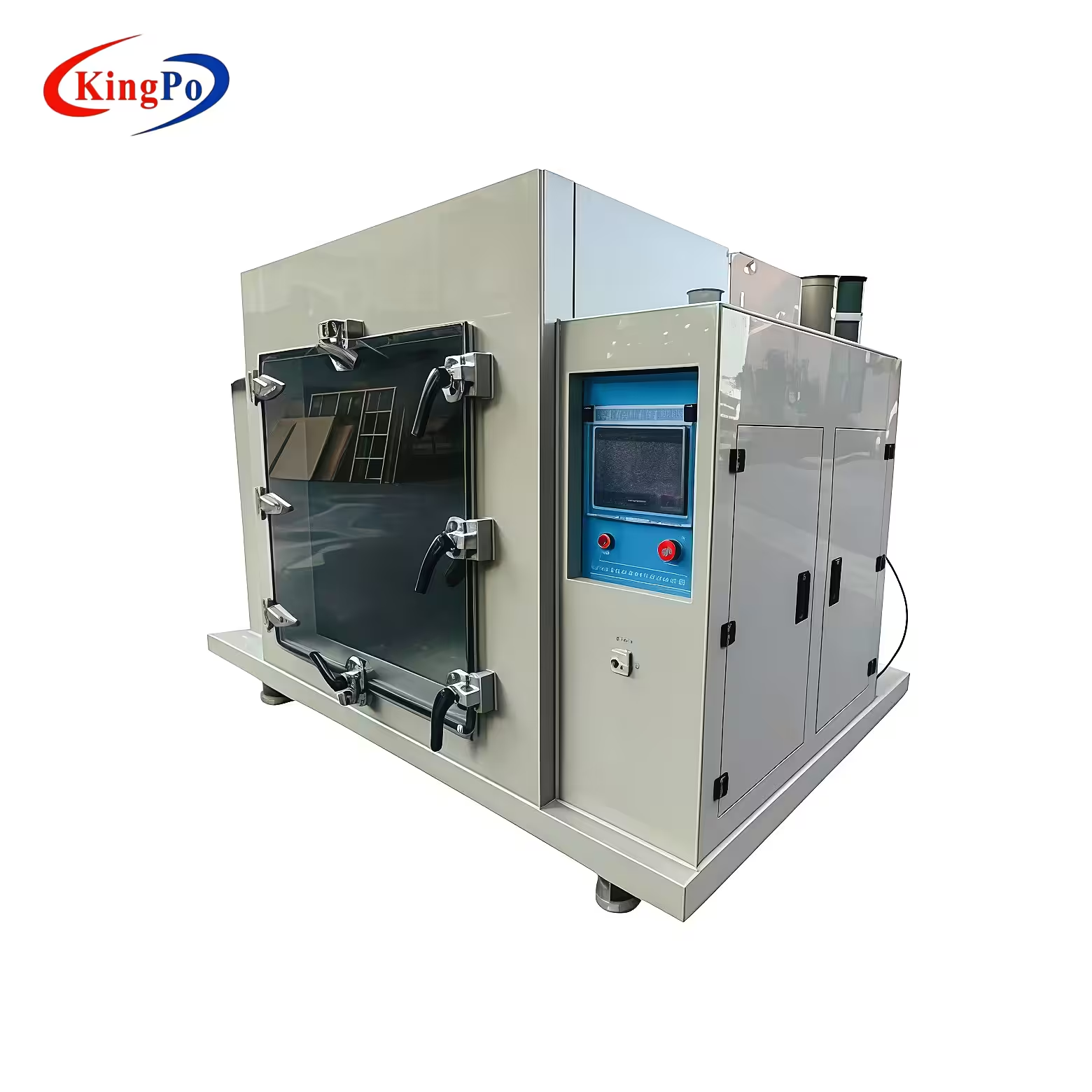
Left-angle view of the IEC 61347-1 Annex D Test Chamber in a laboratory environment
Front view of the Thermally Protected Ballast Heating Test Chamber for IEC 61347-1 Annex D testing
Right-angle view of the Thermally Protected Lamp Controlgear Heating Test Chamber
Left-angle view of the IEC 61347-1 Annex D Test Chamber in a laboratory environment

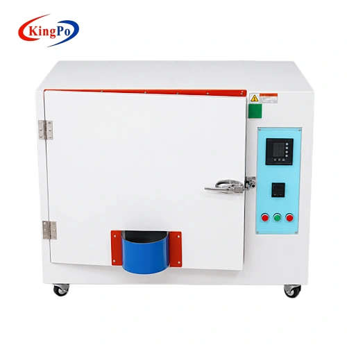
IEC 61347-1 Thermally Protected Ballast Heating Test Chamber

The Thermally Protected Ballast Heating Test Chamber provides a controlled heating environment for testing applicable thermally protected ballasts and lamp controlgear according to IEC 61347-1 Annex D.

  • Equipment Role: The Thermally Protected Ballast Heating Test Chamber provides a dedicated enclosure for thermal protection testing.
  • Standard Alignment: Designed according to the IEC 61347-1 Annex D Test Chamber requirements.
  • Test Focus: Evaluation of thermal protection operation and controlgear surface temperature.
  • Typical Samples: Thermally protected ballasts and applicable lighting controlgear.
  • Primary Users: Certification laboratories, ballast manufacturers and lighting product laboratories.
  • System Scope: Used with suitable power, load and temperature measurement equipment.
  • Related Product Term: Thermally Protected Lamp Controlgear Heating Test Chamber.

Thermally Protected Ballast Heating Test Chamber Product Overview

The Thermally Protected Ballast Heating Test Chamber is a purpose-built enclosure for heating tests performed on ballasts and lamp controlgear incorporating thermal protection.

Unlike a general forced-air temperature chamber, the equipment uses the enclosure dimensions, lower heating zone, raised test platform and natural air circulation arrangement defined for the IEC 61347-1 Annex D test setup. These structural conditions influence heat transfer around the controlgear and help laboratories maintain a consistent test environment.

During testing, the Thermally Protected Ballast Heating Test Chamber holds the controlgear in its specified operating position while it is connected to the required external power supply and lamp load. Chamber temperature, controlgear surface temperature and thermal protection operation can then be observed according to the test procedure.

For broader lighting controlgear applications, the equipment may also be described as a Thermally Protected Lamp Controlgear Heating Test Chamber.
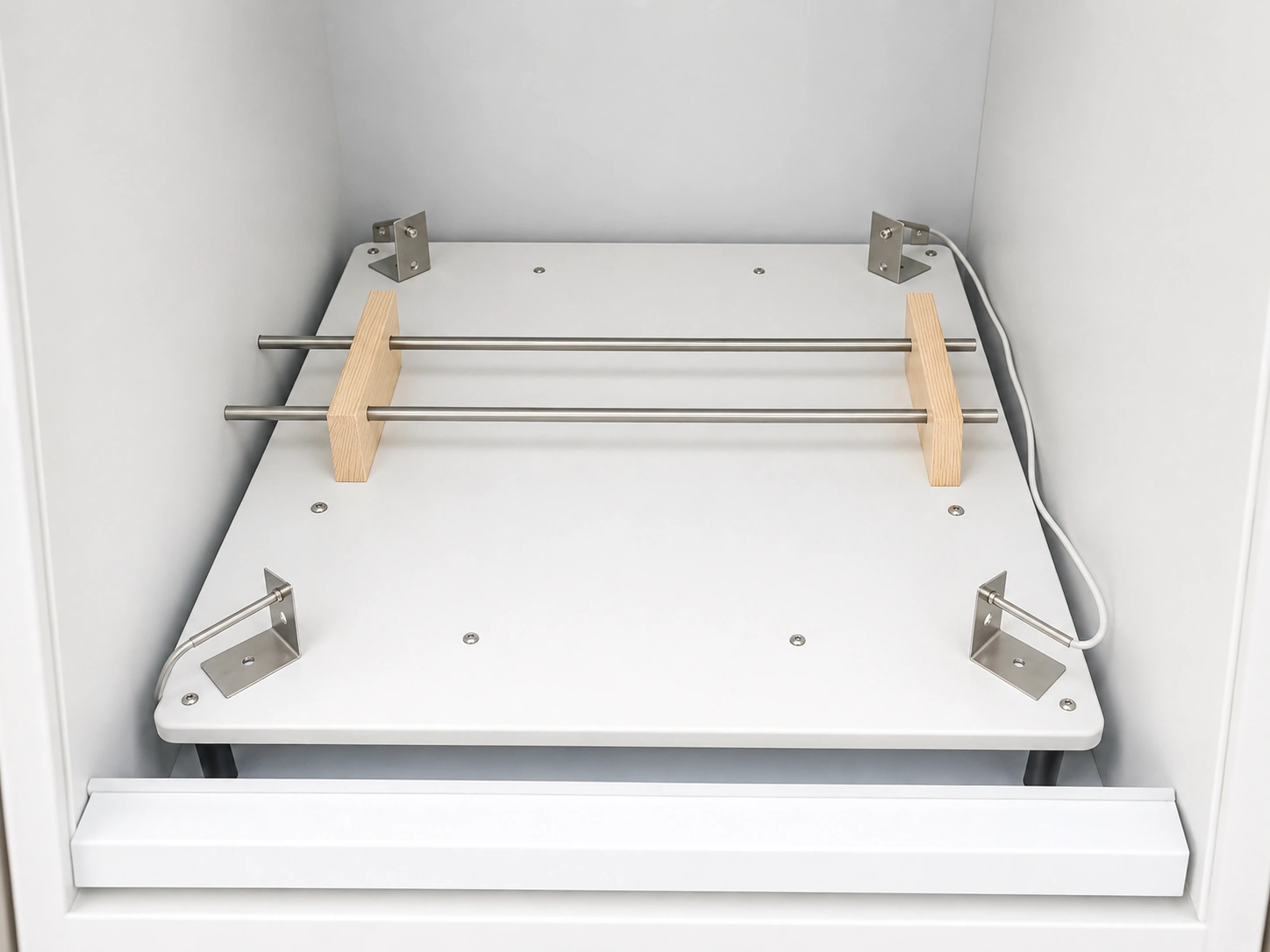
Internal support fixture of the Thermally Protected Ballast Heating Test Chamber

Technical Specifications

IEC 61347-1 ANNEX D

Item Specification
Product Name Thermally Protected Ballast Heating Test Chamber
Applicable Standard IEC 61347-1 Annex D Test Chamber
Internal Test Compartment 610 mm × 610 mm × 610 mm
External Dimensions 660 mm × 660 mm × 760 mm
Test Floor 560 mm × 560 mm
Air Space Around Test Floor 25 mm
Enclosure Construction 25 mm thick heat-resistant material
Lower Heater Compartment 75 mm high
Heating Elements Four strip-type heaters, 300 W each
Heater Surface Reference Approximately 40 mm × 300 mm
Air and Cable Opening 150 mm × 150 mm with aluminium shield
Temperature Control PID controller with thermocouple feedback
Test Temperature 65 °C
Internal Arrangement Manufactured according to Figure D.1

IEC 61347-1 Annex D Test Chamber Compliance

The Thermally Protected Ballast Heating Test Chamber is designed around the enclosure structure and heating arrangement specified in IEC 61347-1 Annex D.

The IEC 61347-1 Annex D Test Chamber requirements define the physical test environment used to evaluate thermal protection incorporated into suitable lamp controlgear.

Enclosure

Defines the chamber construction, internal dimensions and heat-resistant wall structure.

Heating

Specifies the lower heater compartment and strip-heater arrangement.

Positioning

Defines the position and support arrangement of the controlgear under test.

Measurement

Covers ambient and controlgear case-temperature measurement conditions.

The same enclosure can serve as a Thermally Protected Lamp Controlgear Heating Test Chamber for suitable controlgear tested under the Annex D arrangement.

Purpose-Built Enclosure Design
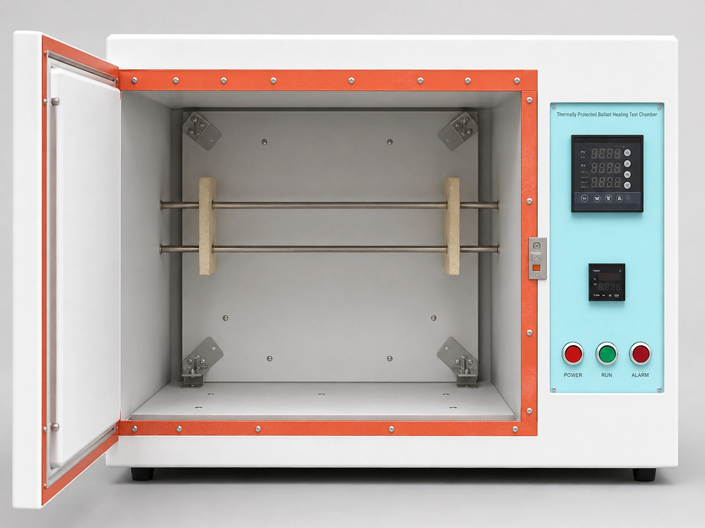
Open view of the IEC 61347-1 Annex D Test Chamber with its internal fixture and control panel

The Thermally Protected Ballast Heating Test Chamber uses a dedicated construction because enclosure size, heater position, airflow, sample support and sensor location can influence the test result. Following the IEC 61347-1 Annex D Test Chamber structure helps maintain a consistent physical test arrangement.

Defined Test Space

A 610 mm cubic compartment provides the standard test area for the controlgear.

Natural Air Circulation

The raised floor and perimeter gap allow heated air to circulate without forced airflow.

Lower Heating Zone

Four strip heaters are positioned below the test floor in a separate compartment.

Shielded Opening

The lower opening supports airflow and cable routing while limiting direct drafts.

Test Objective and Procedure

The Thermally Protected Ballast Heating Test Chamber creates the heated environment required to evaluate the operation of thermal protection incorporated into applicable ballasts and lamp controlgear.

1
Condition the Sample

Place the non-energized controlgear inside the enclosure.

2
Install the Controlgear

Position the sample in its normal operating orientation.

3
Connect the Load

Connect the rated power supply and intended lamp load.

4
Set the Temperature

Maintain the test chamber at 65 °C.

5
Monitor Temperature

Measure the required controlgear surface temperatures.

6
Observe Protection

Record the operation of the thermal protection device.

Heating Chamber Construction

The Thermally Protected Ballast Heating Test Chamber combines a standard-sized test space with a lower heating compartment and a controlled natural airflow path.

Test Compartment

The internal compartment measures 610 mm × 610 mm × 610 mm and uses 25 mm thick heat-resistant enclosure material.

Raised Test Floor

The 560 mm × 560 mm floor leaves a 25 mm air space around the platform, allowing heated air to rise naturally into the test area.

Lower Heater Compartment

A 75 mm high compartment contains four 300 W strip-type heating elements with an approximate heating surface of 40 mm × 300 mm each.

Shielded Opening

The 150 mm × 150 mm lower opening provides the airflow path and cable access. An aluminium shield limits the influence of direct drafts.

Temperature Control

A PID controller with thermocouple feedback regulates the heating elements and maintains the 65 °C test temperature.

Sample Positioning and Temperature Measurement

The Thermally Protected Ballast Heating Test Chamber accommodates the controlgear in its normal operating position at the centre of the test compartment.

Sample Support

The controlgear is supported 75 mm above the test floor using two 75 mm wooden blocks.

Electrical Connection

Wiring is routed through the lower opening, while connected lamps remain outside the enclosure.

Ambient Measurement

Ambient sensors are positioned away from direct wall and heater radiation.

Case Temperature

Thermocouples are attached to the required controlgear surface locations.

The shielded opening should not be exposed to strong drafts or rapid air currents during testing.

Thermally Protected Ballast Heating Test Chamber Features

IEC 61347-1 Annex D arrangement
610 mm cubic test space
25 mm heat-resistant walls
Natural air circulation
Four 300 W strip heaters
PID temperature control
Shielded cable opening
65 °C test temperature

Typical Laboratory Applications

Certification Testing

The Thermally Protected Ballast Heating Test Chamber supports repeatable IEC 61347-1 Annex D testing in certification and third-party laboratories.

Ballast Development

Manufacturers use the Thermally Protected Ballast Heating Test Chamber for thermal protection evaluation, product development and pre-compliance testing.

Lighting Quality Control

The Thermally Protected Ballast Heating Test Chamber helps lighting manufacturers assess ballasts intended for integration into finished luminaires.

Laboratory Integration

A Thermally Protected Lamp Controlgear Heating Test Chamber can be integrated with power supplies, lamp loads and temperature measurement instruments.

System Configuration and Laboratory Use

The Thermally Protected Ballast Heating Test Chamber provides the enclosure, heating arrangement, natural airflow structure and PID temperature regulation required for the heating test.

Chamber System

  • Heat-resistant test enclosure
  • Lower strip-heater arrangement
  • PID temperature controller
  • Shielded airflow opening

Supporting Test Equipment

  • Controlgear power supply
  • Rated lamps or electrical load
  • Surface thermocouples
  • Temperature measuring instrument

Test Value for Laboratories and Manufacturers

The Thermally Protected Ballast Heating Test Chamber reproduces the dedicated Annex D enclosure arrangement more accurately than an ordinary forced-air oven.

It supports consistent controlgear positioning, defined natural airflow and controlled heating for certification testing, product development and lighting quality evaluation.

Related KINGPO Test Equipment

The Thermally Protected Ballast Heating Test Chamber can be used with related lighting controlgear safety and temperature measurement equipment.
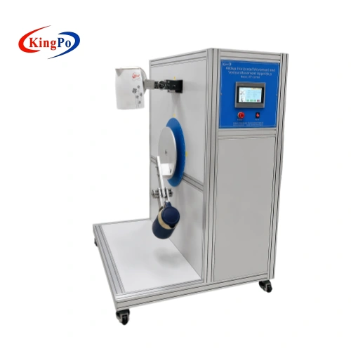
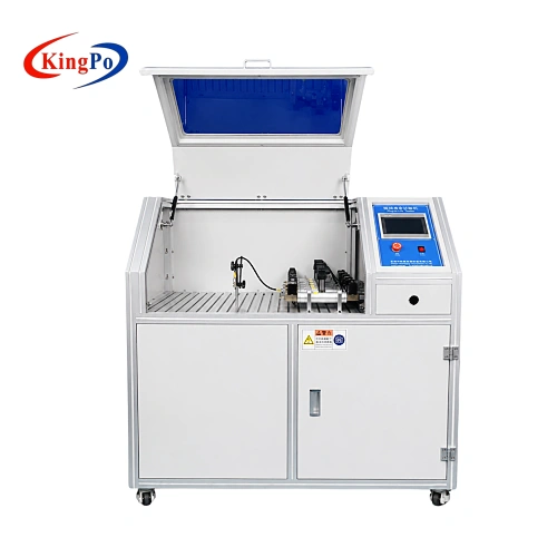
Thermally Protected Ballast Heating Test Chamber accessories
IEC 61347-1 Annex D Test Chamber components
Lamp controlgear measurement equipment
IEC 61347-1 long-duration pulse test equipment
AC or DC controlgear power supplies
Temperature measurement instruments

Compliance & Regulatory Assurance

The Thermally Protected Ballast Heating Test Chamber is designed to support heating tests for thermally protected ballasts and applicable lamp controlgear according to IEC 61347-1 Annex D. Its 610 mm cubic test compartment, 25 mm heat-resistant enclosure, lower heater zone, four 300 W strip heaters, shielded opening, PID temperature control and 65 °C test temperature provide the defined thermal environment required for the test arrangement.

Final compliance depends on the complete laboratory setup, including sample positioning, wooden support blocks, rated power supply, external lamp load, thermocouple placement and protection from drafts. The chamber provides the controlled heating environment, while test results are determined through correct operation, measurement and evaluation in accordance with the applicable procedure.

Technical Datasheet
IEC 61347-1 Annex D Thermally Protected Ballast Heating Test Chamber
Product overview, technical specifications, test arrangement, temperature control, laboratory applications and equipment details.

Download PDF

Technical Inquiry & Expert Support

To evaluate the appropriate Thermally Protected Ballast Heating Test Chamber configuration for your laboratory, please provide the project information below when sending an inquiry. This allows the test standard, controlgear type, electrical setup and measurement requirements to be reviewed before quotation.

Information Needed Description
Applicable Standard IEC 61347-1 Annex D and the test procedure used by your laboratory.
Controlgear Type Thermally protected ballast or other applicable lamp controlgear, including the thermal protection method.
Sample Information Sample dimensions, normal operating position and required support arrangement inside the chamber.
Electrical Test Setup Rated voltage, frequency, intended lamp load and connection arrangement used during testing.
Temperature Measurement Ambient and case-temperature measurement points, thermocouple arrangement and laboratory recording method.
Documentation Needs Datasheet, operating manual, dimensional inspection record or other project documentation required by your laboratory.
Note:
The complete test arrangement should be reviewed together with the chamber, power supply, lamp load, sample positioning and temperature measurement method.

IEC 61347-1 Annex D Test Chamber Heating Enclosure For Thermally Protected Ballasts

Thermally Protected Ballast Heating Test Chamber Detail Display

Thermally Protected Ballast Heating Test Chamber FAQ

What is the main purpose of the Thermally Protected Ballast Heating Test Chamber?
The Thermally Protected Ballast Heating Test Chamber provides a controlled heating environment for evaluating thermal protection incorporated into ballasts and applicable lamp controlgear. It allows laboratories to monitor controlgear surface temperature and thermal protector operation under the enclosure, airflow, sample-positioning and heating conditions associated with IEC 61347-1 Annex D.
Which standard is this heating test chamber designed for?
The chamber is designed according to the IEC 61347-1 Annex D Test Chamber arrangement. Annex D describes the enclosure construction, heater arrangement, controlgear operating conditions, sample position and temperature measurement method used when carrying out heating tests on thermally protected lamp controlgear.
What types of controlgear can be tested in this chamber?
The equipment is primarily intended for thermally protected ballasts and other applicable lamp controlgear incorporating thermal protection. Suitability depends on the controlgear design and the test procedure applied by the laboratory. It should not be treated as a universal test chamber for every ballast or LED driver.
How is this chamber different from a general temperature chamber?
A general chamber may use forced-air circulation, which can create a different heat-transfer pattern around the sample. This Thermally Protected Lamp Controlgear Heating Test Chamber uses a raised floor, lower heating compartment, perimeter air gap and shielded opening to reproduce the natural airflow arrangement described in IEC 61347-1 Annex D.
How does the chamber create the required heating environment?
Four 300 W strip-type heaters are installed in a 75 mm compartment below the test floor. Heated air rises through the 25 mm space surrounding the platform and circulates naturally through the 610 mm cubic test compartment. A shielded lower opening provides the defined airflow path and cable access.
What test temperature and control method does the equipment use?
The Thermally Protected Ballast Heating Test Chamber operates at a specified test temperature of 65 °C. A PID controller with thermocouple feedback regulates the four heating elements. This arrangement provides controlled heating while retaining the natural air circulation characteristics of the IEC 61347-1 Annex D enclosure.
Does the chamber include everything required to perform the complete test?
The chamber provides the enclosure, heating system, airflow structure and temperature control. A complete laboratory setup also uses a suitable power supply, intended lamp or electrical load, surface thermocouples and temperature measurement instruments. These components support sample operation, temperature monitoring and observation of the thermal protection device.
How should the controlgear be positioned during testing?
The controlgear is placed centrally in the test compartment in its normal operating position. It is supported 75 mm above the test floor using two 75 mm wooden blocks. Electrical connections pass through the lower opening, while connected lamps are positioned outside the enclosure in accordance with the Annex D arrangement.
How are ambient and controlgear case temperatures measured?
Ambient temperature is measured at suitable positions away from direct wall and heater radiation, approximately level with the centre of the controlgear. Case temperatures are normally measured using thermocouples attached to the required surface locations. Sensor placement should remain consistent throughout the test to support reliable temperature evaluation.
Does the chamber automatically determine whether a sample complies with IEC 61347-1?
No. The IEC 61347-1 Annex D Test Chamber provides the required physical heating environment but does not independently issue a pass-or-fail result. Compliance evaluation also depends on the electrical setup, sample position, lamp load, temperature measurements, thermal protector operation and the acceptance criteria applied by the testing laboratory.

Related Products

Related News

Abstract / Technical Summary Our LV 124 K-12 thermal shock test chamber is a specialized ice water splash thermal shock […]

IEC Standards and Definitions ensure global safety, reliability, and compatibility for electrical and electronic products across industries.

Abstract & Technical Summary IEC 62368-1 foreign object detection (FOD) testing assesses wireless power transmitter safeguards against excessive metal object […]

For plastic insulation frames, given the high heat generated by the copper wires and iron core, if the flame retardant […]

Environmental test chamber solutions boost product reliability by simulating real-world stress, identifying weaknesses, and ensuring consistent performance.

Abstract Thermage, a non-invasive radiofrequency (RF) skin tightening technology, is widely used in medical aesthetics. With operating frequencies increasing to […]

Scroll to Top

Get A Free Quote Now !

Contact Form
If you have any questions, please do not hesitate to contact us.