The glow wire test (GWT) is a cornerstone fire hazard assessment method in electrical and electronic product safety, as defined by IEC 60695-2 series standards. Laboratories participating in proficiency testing (PT) under ISO/IEC 17025 accreditation frequently encounter non-conformities stemming from equipment inconsistencies, procedural deviations, calibration drifts, and environmental influences. This extensively updated guide (February 2026) focuses on the KINGPO KP-FT01 glow wire tester, a compliant apparatus widely adopted for IEC 60695-2-10, GB/T 5169.10, UL 746A, and related requirements. It provides exhaustive analysis of the heating principle, root causes of PT failures, detailed operational and maintenance procedures from manufacturer documentation, quantitative mitigation strategies, and best practices to achieve reproducible results.
This guide draws on IEC standards, KINGPO KP-FT01 operation manual (2022 edition), practical laboratory experiences, mathematical modeling of Joule heating, uncertainty budgets, and PT observations. It aims to assist testing engineers, quality managers, and accreditation bodies in minimizing z-score outliers and maintaining accreditation scope for IEC 60695-2-11 (GWT), IEC 60695-2-12 (GWFI), and IEC 60695-2-13 (GWIT).
 1")
1. Introduction to Glow Wire Testing and Proficiency Testing Requirements
1.1 Historical Development and Regulatory Evolution
The glow wire test originated in the 1970s within IEC initiatives to simulate glowing element faults in household appliances, such as overloaded resistors or faulty connections. Initial focus was on end-product ignition risk, later expanding to material classification (GWFI/GWIT). The current IEC 60695-2-10:2021 standard specifies apparatus design and common procedures, while IEC TR 60695-2-16:2025 summarizes recent round-robin interlaboratory comparisons, identifying key variability sources including voltage fluctuations, thermocouple drift, and inconsistent application parameters.
Proficiency testing, mandated by ILAC and national bodies (e.g., CNAS, UKAS, DAkkS), circulates identical blind samples for comparison against consensus or reference values. Unsatisfactory performance (z-score > |3| or En >1) necessitates root cause analysis, corrective actions, and potential scope suspension. In 2025-2026 PT rounds, approximately 20-30% of participating laboratories failed due to temperature deviations exceeding ±10°C or misrecorded flame persistence times.
1.2 Importance in Product Safety and Market Access
GWT evaluates non-metallic materials’ response to a glowing element, assessing ignition propensity, flame spread, and self-extinguishing behavior without open flame sources. This distinguishes it from needle flame or UL 94 tests. Failures can trigger product recalls, liability issues, or market bans. In 2026, with surging IoT, EV, and smart home components, precise GWT compliance is essential for IEC 60335 household appliances, GB 4943 IT equipment, and UL 746A polymeric materials.
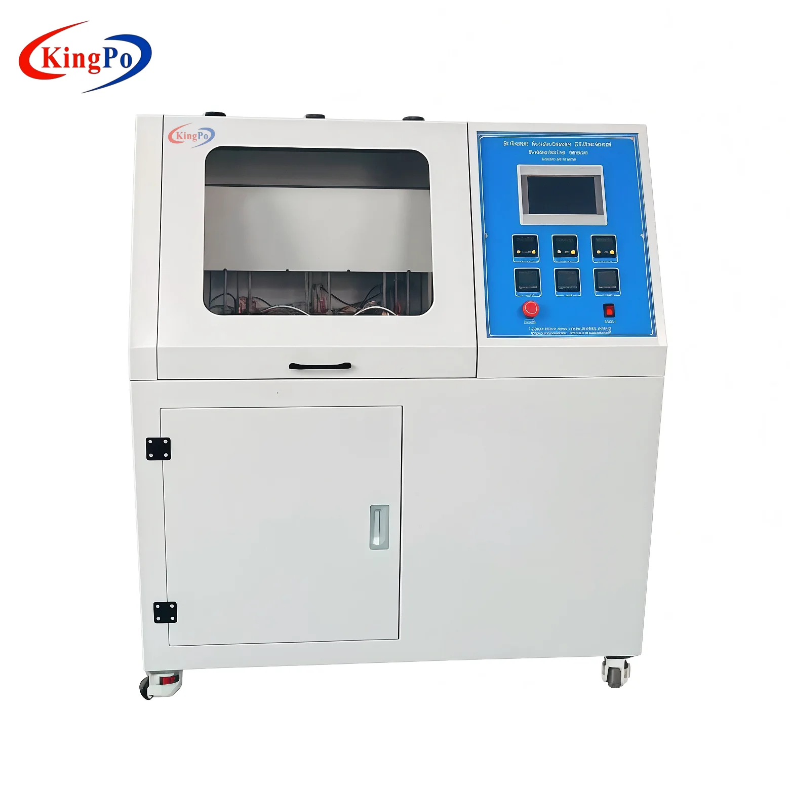
Laboratories using KINGPO KP-FT01 benefit from its single-chip microcontroller + touchscreen control, high-precision independent thermometer, and one-key operation, which enhance anti-interference and testing efficiency, contributing to better PT reproducibility.
1.3 Common PT Objectives and Metrics
PT evaluates:
- Temperature stability (±10°C tolerance, often ±2°C in advanced systems).
- Application force (0.95 ±0.1 N or 1.0 ±0.2 N per standard).
- Penetration depth (7 ±0.5 mm).
- Timing (30 s ±1 s glow time; Ti/Te automatic/manual recording).
- Observations: Ignition time (Ti), extinction time (Te), dripping behavior, tissue paper ignition.
Metrics include z-scores, robust standard deviations, and En values. Typical samples include polyamide or polycarbonate at 750-960°C.
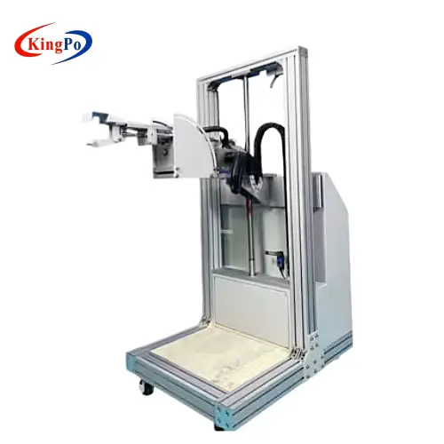
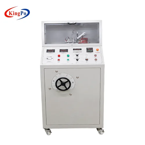
2. Detailed Heating Principle of the KINGPO KP-FT01 Apparatus
2.1 Electrical Power Supply and Transformer Configuration
The KP-FT01 operates on standard 220 V AC mains, stepped down via a high-capacity transformer to low voltage/high current for resistive heating. Power follows Joule’s law: P = I²R, where R is the glow wire resistance (≈0.05–0.1 Ω at ambient).
Mains fluctuations (±10%) directly affect secondary current and temperature. The system uses independent electronic control with high-precision thermometer for enhanced stability and anti-interference over PLC-based designs.
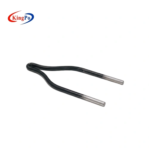
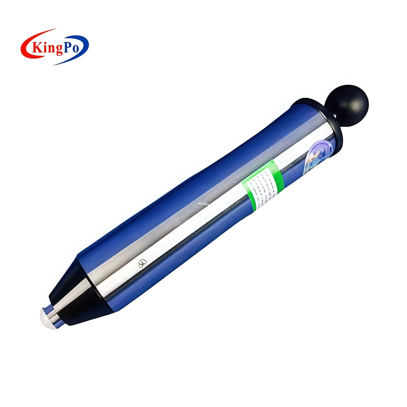
2.2 Glow Wire Material and Geometry
Ni80/Cr20 alloy wire, Φ4 mm diameter, U-shaped per IEC 60695-2-10. Penetration depth: 7 ±0.5 mm. The U-head is consumable, requiring replacement on signs of wear.
 2")
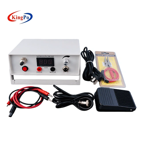
2.3 Thermocouple Integration and Temperature Measurement
Imported K-type armored thermocouple (Φ1 mm, ±0.05% accuracy) embedded in the tip. Temperature range: up to 1050°C ±0.1%. PID control maintains stability, with display resolution supporting precise adjustments.
2.4 Joule Heating Dynamics and Equilibrium
Heating dynamics follow: generated heat = losses (radiation σ ε A T⁴ + convection h A (T – Tₐ)). Equilibrium temperature correlates with current. Reference table (manual Appendix A) shows approximate values (e.g., 960°C ≈136 A), but calibration targets 120 A for system accuracy, accounting for wire condition and setup variations.
3. Primary Sources of Error in Glow Wire Testing
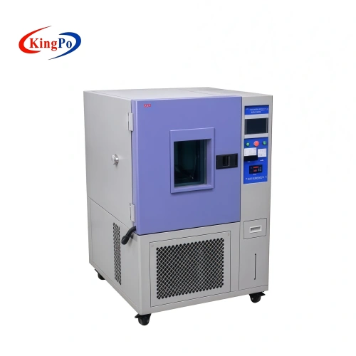
3.1 Impact of Mains Voltage Fluctuations
Voltage drops reduce current, lowering temperature (e.g., 5% drop → ~5-10 A deviation at high levels → tens of °C shift).
3.2 Glow Wire Material and Dimensional Inconsistencies
Oxidation, cracks, or thinning increases resistance. Replacement criteria: surface cracks, significant current deviation from reference, tip dimension ≤97.5% original.
3.3 Calibration and Instrumentation Drift
Thermocouple drift: resistance >200 Ω signals replacement. Current display requires calibration to 120 A via clamp meter.
3.4 Procedural and Operator Variability
Inconsistent 7 mm limit adjustment, force application, or timing. Environmental drafts affect heat loss.
4. Common Non-Conformities Observed in Proficiency Testing
Typical failures:
- Temperature inaccuracies (z >3 in 25% of labs).
- Misjudged Ti/Te.
- Calibration non-compliance.
Example table:
| Parameter | Assigned Value | Lab Result | z-Score | Status |
|---|---|---|---|---|
| GWIT at 960°C | No ignition | Ignition | 4.2 | Unsatisfactory |
| Flame persistence (Te) | 22 s | 35 s | 3.8 | Unsatisfactory |
| Temperature stability | ±8°C | ±18°C | 3.5 | Unsatisfactory |
Root causes: voltage (40%), calibration drift (30%), operator error (20%).
5. Root Cause Analysis Methodologies
5.1 5 Whys and Fishbone Diagrams
Example: Low temperature → Voltage sag → No stabilizer → Cost priority.
Fishbone: Man (training), Machine (calibration), Material (wire), Method (procedure), Measurement (current), Environment (drafts).
5.2 Uncertainty Budget Example
| Source | Standard Uncertainty (°C) | Distribution |
|---|---|---|
| Thermocouple calibration | 2.5 | Normal |
| Voltage fluctuation | 4.0 | Rectangular |
| Current measurement | 1.8 | Normal |
| Combined u | 5.1 | – |
| Expanded U (k=2) | 10.2 | – |
6. Effective Solutions and Mitigation Strategies
6.1 Voltage Stabilization Techniques
Use AVR/CVT/UPS for ±1% regulation.
6.2 Glow Wire Quality Assurance
Source certified wire. Replace on cracks, current deviation, or dimension reduction. Polish oxidized contacts.
6.3 Calibration Procedures: KINGPO KP-FT01 Specific
Set GLOW TIME to 99 s to enter calibration mode:
- Temperature offset: Adjust display to match actual (positive/negative input).
- Current: Use clamp meter on heating cable, heat to target, input 120 A measured value.
- Upper limit: 1200°C.
- Factory parameters: Unmodifiable.
Silver foil verification at 960°C for system check. 3")
6.4 Current Monitoring and Verification
Compare display with clamp meter; >2% discrepancy → recalibrate.
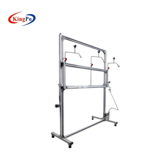
6.5 Operational Best Practices: 7 mm Limit Adjustment
Detailed steps from manual:
- Loosen limit base screw (4).
- Move base to rightmost.
- Loosen limit post screw (2).
- Move post leftmost, tighten (2).
- Install sample, move to rightmost contact.
- Move base leftmost to contact cart, tighten (4).
- Loosen (2), move post rightmost.
6.6 Test Procedure: Step-by-Step (KP-FT01)
- Set GLOW TIME 30 s.
- Place tissue-wrapped pine board + drip tray under U-head.
- Clamp sample.
- Adjust 7 mm limit.
- Move cart leftmost.
- Activate heating.
- Adjust current to target temperature.
- Preheat 5 min, fine-tune.
- Press START. 10-11. Press control box on ignition (Ti), extinction (Te).
- Auto exhaust post-test.
- Clean U-head residue (avoid damaging thermocouple).
6.7 Maintenance and Troubleshooting
- Thermocouple: Replace if >200 Ω.
- U-head: Replace on cracks/deviation/thinning; polish oxidation.
- Common faults: No heating (oxidized contacts, damaged head); overtemp (raise limit).
7. Case Studies from Proficiency Testing Rounds
Voltage-induced failures resolved with AVR. Calibration drift fixed via 120 A verification and offset adjustment.
8. Advanced Topics and Future Trends (2026 Perspective)
Digital logging integration, AI-assisted calibration.
9. Best Practices for Laboratories
Annual calibration, SOPs with 120 A check, preventive maintenance.
10. Conclusion
Leveraging KINGPO KP-FT01’s features—precise control, one-key operation, and calibration to 120 A—laboratories can significantly reduce PT non-conformities, ensuring accurate fire safety assessments.