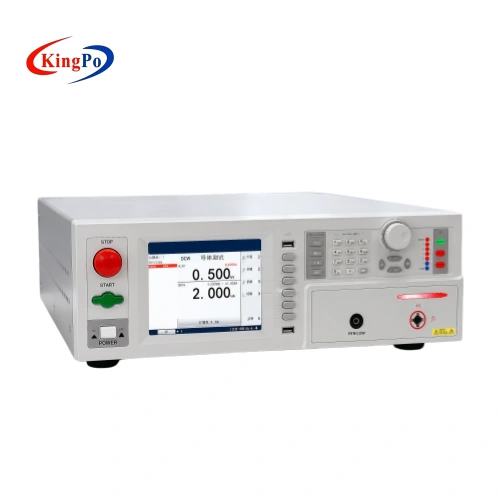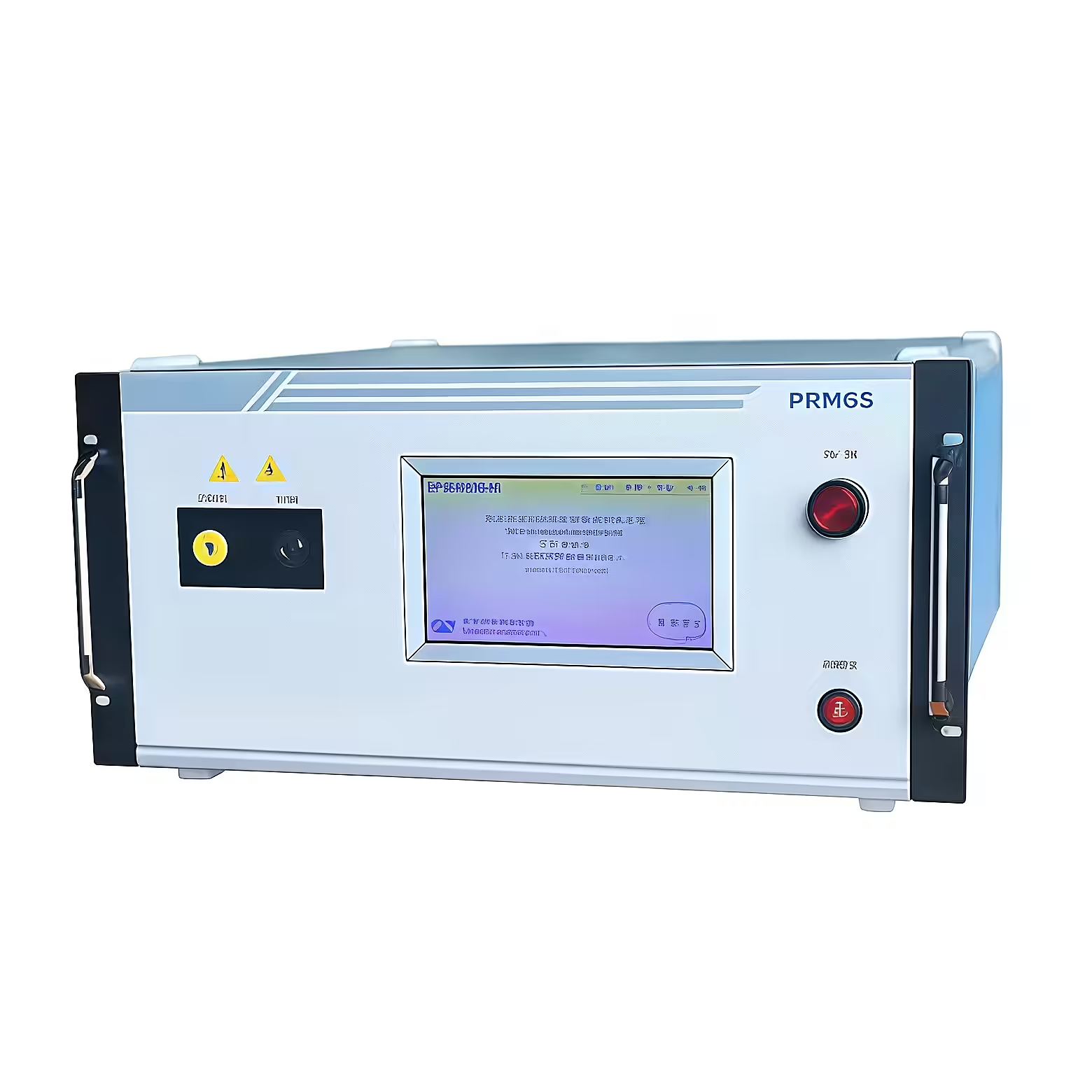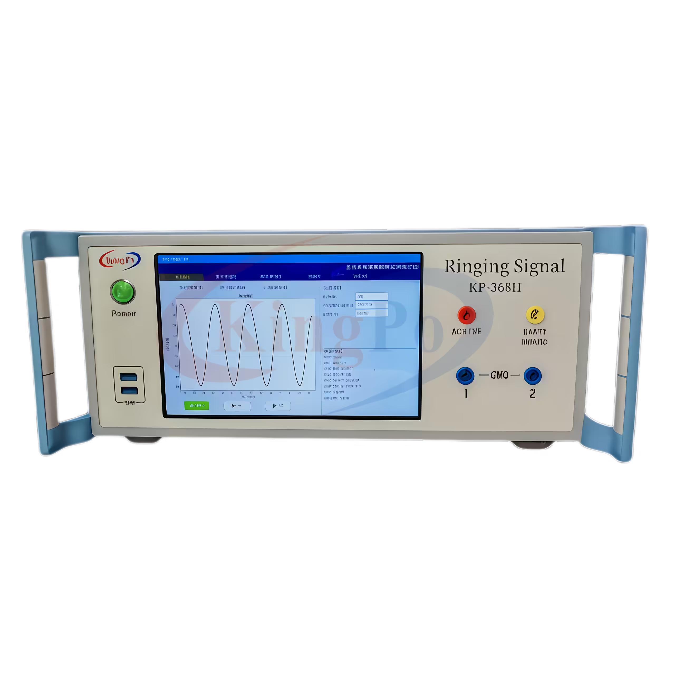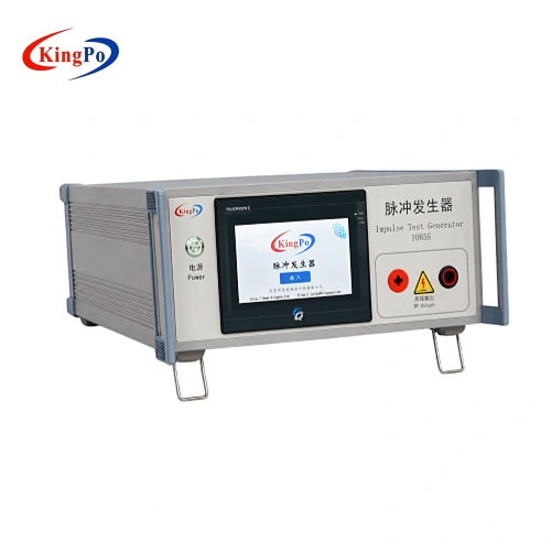
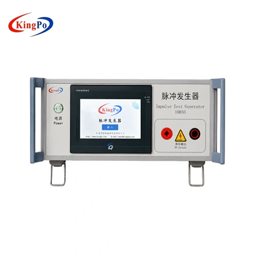
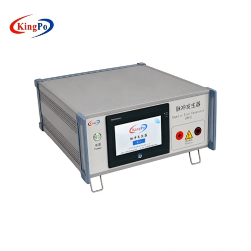
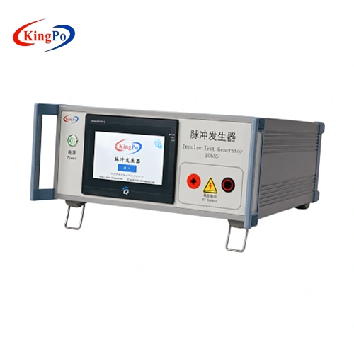
The KP-1065S is an IEC 62368-1 Figure D.2 Pulse Voltage Generator designed for Table D.1 Circuit 3 related testing. It provides controlled high-voltage surge and HVDC output for antenna interface insulation withstand verification in AV/ICT equipment.
This model is suitable for safety laboratories, AV/ICT equipment manufacturers and R&D teams working with IEC 62368-1 Figure D.2 antenna interface test requirements.
For correct selection, buyers should confirm the applicable standard edition, Figure D.2 / Table D.1 Circuit 3 requirement, output voltage level, DUT interface, test timing and monitoring or calibration needs before ordering.
Technical Specifications
The main specifications of the KP-1065S IEC 62368-1 Figure D.2 Pulse Voltage Generator are organized below for quick technical and purchasing review.
Output and Energy Storage
| Item | Specification |
|---|---|
| Product Model | KP-1065S |
| Applicable Standard | IEC 62368-1 Annex D, Figure D.2 / Table D.1 Circuit 3 |
| Circuit Reference | Table D.1 Circuit 3 |
| Test Application | Antenna interface pulse voltage, surge and HVDC withstand testing |
| Output Surge Voltage | 0–10 kV |
| Voltage Resolution | 0.01 kV |
| Digital Display Accuracy | ±5% ±2 digits |
| Charging Capacitance | 1 nF / 30 kV ±5% |
Timing and Test Count
| Item | Specification |
|---|---|
| Charging Time Setting | 1–999 s |
| Charging Time Accuracy | ±3% |
| Discharge Time Setting | 1–999 s |
| Discharge Time Accuracy | ±3% |
| Number of Tests | 1–9999 times |
| Test Count Accuracy | ±1 time |
Control, Monitoring and Power
| Item | Specification |
|---|---|
| Control System | Panasonic PLC / Panasonic C14R |
| Display and Operation | 7-inch color touchscreen |
| Touchscreen Model | TK6070iH |
| Monitoring Output | Oscilloscope monitoring port |
| Voltage Divider Ratio | 1:1000 |
| Protection Function | Overvoltage protection |
| High-Voltage Transformer Power | ≥150 VA |
| Working Power Supply | AC 220 V ±10%, 50 Hz ±2 Hz |
Figure D.2 and Table D.1 Circuit 3 Reference
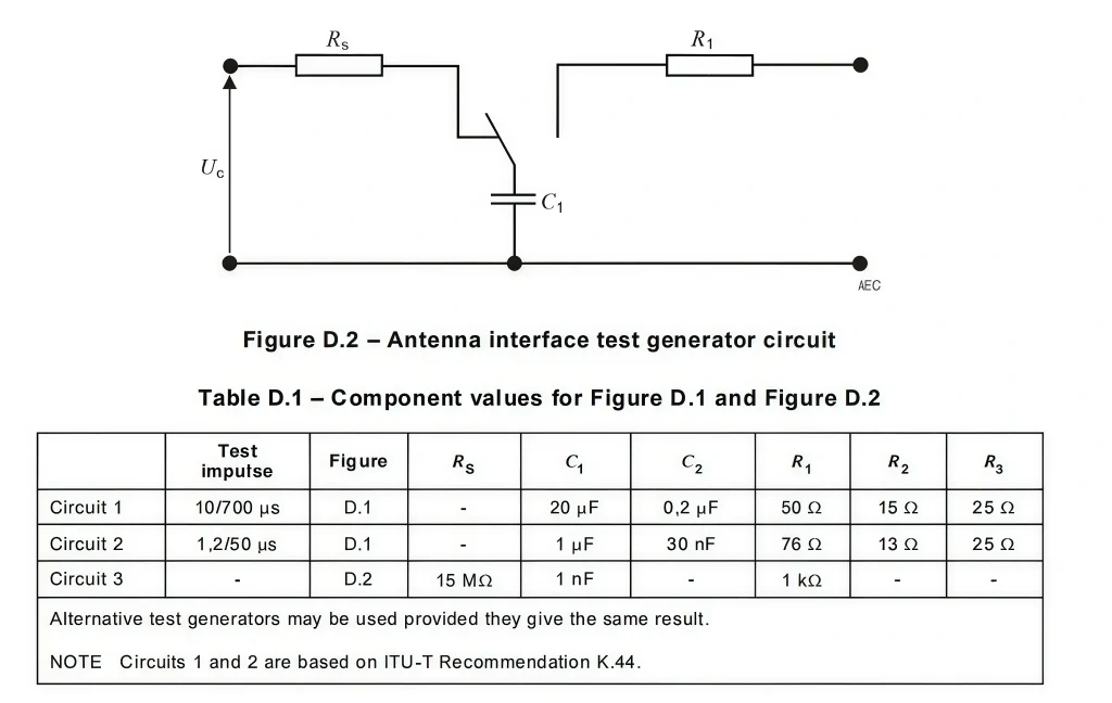
IEC 62368-1 Annex D includes different pulse and impulse generator circuits. For the KP-1065S, the relevant reference is Figure D.2, with component values corresponding to Table D.1 Circuit 3.
This makes the KP-1065S different from Figure D.1 impulse generators used for Table D.1 Circuit 1 and Circuit 2.
Note:
Difference Between Related IEC 62368-1 Test Generators
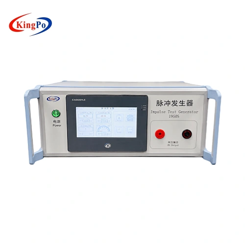
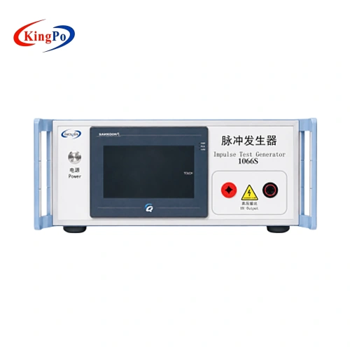
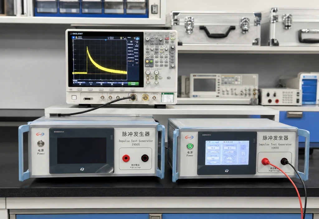
KP-1065S, KP-1950S and KP-1066S are related to IEC 62368-1 high-voltage or pulse testing, but they correspond to different figures, circuits and applications. They should be selected according to the required standard reference rather than grouped as one product.
| Model | Standard Reference | Circuit | Main Purpose |
|---|---|---|---|
| KP-1950S | Figure D.1 / Table D.1 | Circuit 1 and Circuit 2 | 10/700 μs and 1.2/50 μs impulse testing |
| KP-1065S | Figure D.2 / Table D.1 | Circuit 3 | Figure D.2 pulse voltage testing for antenna interface insulation verification |
| KP-1066S | Figure D.3 / Annex D.3 | Electronic pulse generator circuit | Separate Annex D.3 electronic pulse generator application |
Design and Operation Features
| 0–10 kV Surge Voltage Output Supports adjustable high-voltage output with 0.01 kV resolution for different verification stages. |
1 nF / 30 kV Charging Capacitance Matches the key capacitance requirement for Figure D.2 / Table D.1 Circuit 3 related testing. |
| PLC Touchscreen Control Panasonic PLC and 7-inch touchscreen support stable parameter setting and repeatable operation. |
Programmable Test Sequence Charging time, discharge time and test count can be set for repeated verification and quality control. |
| 1:1000 Monitoring Output Provides an oscilloscope monitoring output for voltage or waveform observation using suitable measurement equipment. |
Overvoltage Protection Built-in protection helps improve operational safety during high-voltage pulse and surge testing. |
Oscilloscope Monitoring and Calibration Notes
For voltage parameter calibration or waveform verification, a storage oscilloscope and a suitable high-voltage divider or high-voltage probe are normally required.
The monitoring output uses a 1:1000 voltage division ratio. For example, if the oscilloscope measures a 1 V peak signal at the monitoring output, this corresponds to an output surge pulse voltage of 1000 V.
Actual calibration should be performed according to the laboratory’s quality system, applicable standard edition and selected measurement equipment.
Typical Applications and Test Purpose
The KP-1065S is used for IEC 62368-1 Figure D.2 related pulse voltage testing of AV/ICT equipment, especially antenna interfaces and communication-related ports.
|
|
Test Purpose:
The test may help identify weak insulation paths, insufficient component withstand margin, poor interface protection design, breakdown risk, flashover risk or abnormal response under high-voltage stress.
Buyer’s Selection Notes
Confirm whether the project follows IEC 62368-1, GB4943.1 or another national adoption.
Confirm whether the project requires Figure D.2 and Table D.1 Circuit 3.
Confirm the required output voltage within the 0–10 kV range and whether 1 nF / 30 kV ±5% matches the test requirement.
Confirm the required charging time, discharge time and number of repeated tests.
Confirm whether oscilloscope waveform capture, 1:1000 monitoring output, high-voltage probe measurement, datasheet or calibration document is required.
Typical Operation Workflow
- Confirm the applicable IEC 62368-1 edition and Figure D.2 / Table D.1 Circuit 3 requirement.
- Prepare the DUT and identify the antenna interface or communication port to be tested.
- Confirm the test connection method according to the laboratory procedure.
- Set the required output voltage, charging time, discharge time and number of tests.
- Connect the monitoring output to a storage oscilloscope if waveform observation is required.
- Check grounding, insulation clearance and operator safety conditions before testing.
- Start the programmed test sequence through the touchscreen interface.
- Observe DUT behavior, test status and oscilloscope waveform if applicable.
- Record abnormal discharge, breakdown, flashover, failure or other observations.
- Discharge safely before disconnecting the DUT or test leads.
Safety Note:
High-voltage pulse and surge testing should only be performed by trained personnel under controlled laboratory conditions.
IEC 62368-1 Figure D.2 Pulse Voltage Generator
The KP-1065S is specifically designed for IEC 62368-1 Figure D.2 pulse voltage testing, with the circuit configuration corresponding to Table D.1 Circuit 3.
It is used for antenna interface insulation withstand verification and should not be confused with a general signal generator, an unrelated EMC surge generator, or the KP-1950S Figure D.1 impulse test generator. For correct model selection, the applicable figure, circuit number, voltage range, DUT interface and monitoring requirement should be confirmed before ordering.