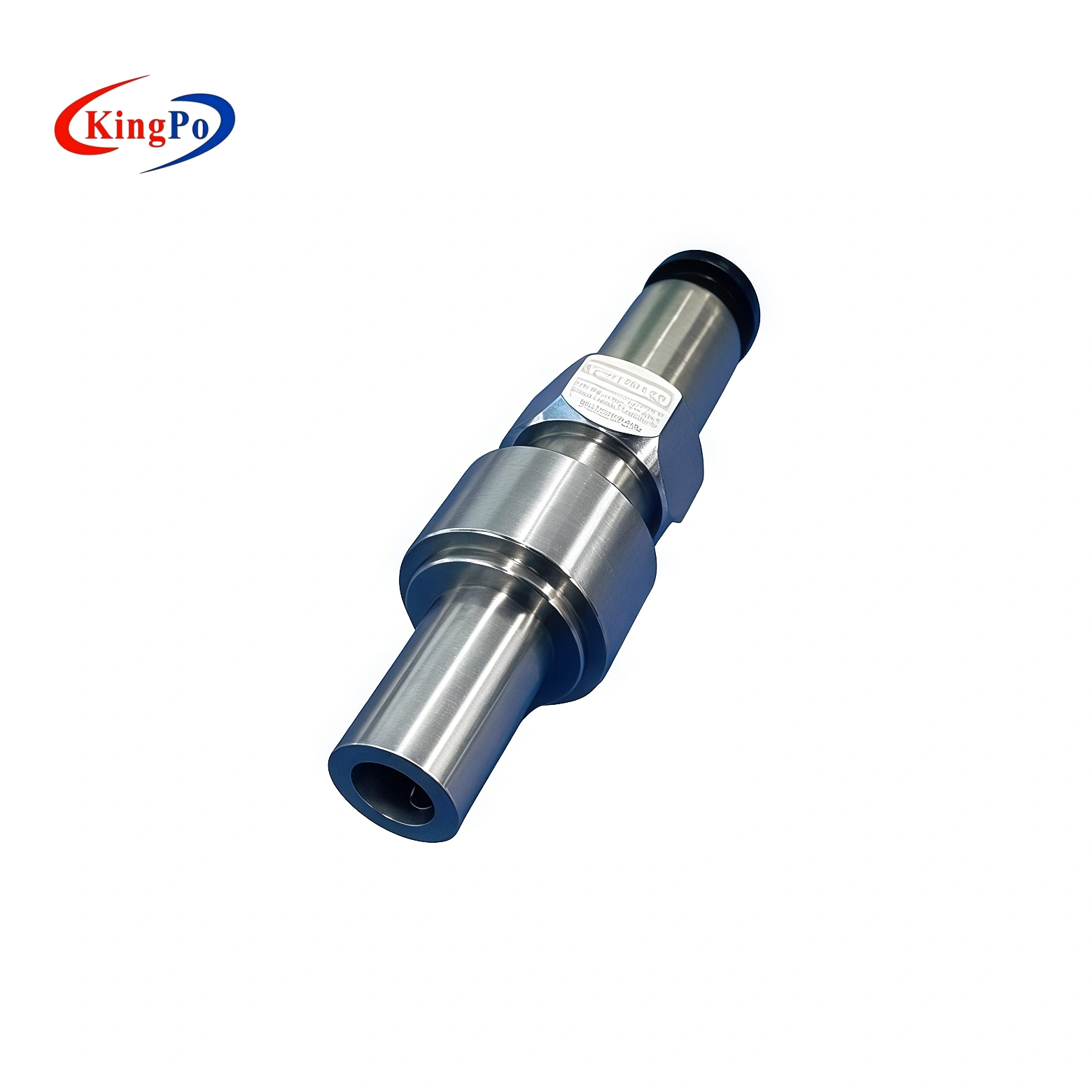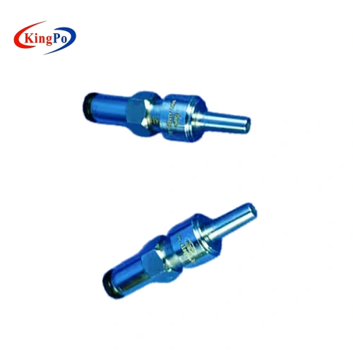
ISO 80369-7 Figure C.6 Male Reference Connector
The ISO 80369-7 Figure C.6 Male Reference Connector is used as a controlled mating component for evaluating female Luer lock connectors. According to the Figure C.6 drawing you provided, this connector is intended for test configurations related to separation from axial load and resistance to overriding.
This product should not be confused with the ISO 80369-7 Figure C.4 Male Reference Luer Lock Connector. C.4 and C.6 are both male reference connector pages, but their test focus and reference configurations are different. C.6 should be selected when the test procedure specifically requires the Figure C.6 male reference connector for female Luer lock connector testing.
The Figure C.6 connector is a precision reference component, not a complete test apparatus. For axial load or overriding resistance testing, it must be used with the appropriate fixture, force application system, measuring device and applicable ISO 80369 test procedure.
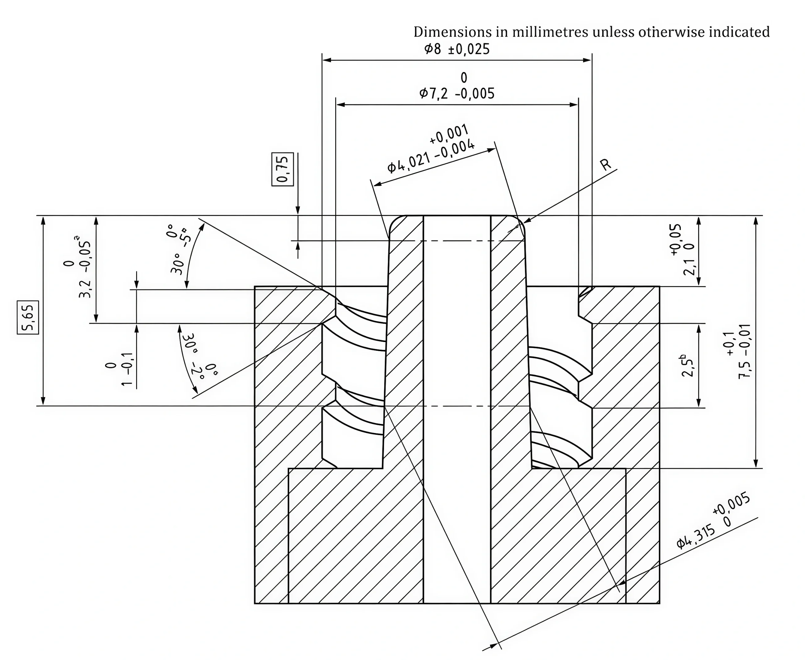
Key Drawing Notes
Based on the ISO 80369-7 Figure C.6 drawing you provided, this product is identified as a male reference connector for testing female Luer lock connector for separation from axial load and resistance to overriding.
| Item | Figure C.6 Note |
|---|---|
| Figure Number | ISO 80369-7 Figure C.6 |
| Reference Connector Type | Male reference connector |
| Test Object | Female Luer lock connectors |
| Test Purpose | Separation from axial load and resistance to overriding |
| Thread Note | Double-start, right-hand thread of 2.5 mm pitch |
| Key Distance Note | Maximum distance from the tip of the male Luer lock connector to the first complete profile of the internal thread should follow the referenced Table B.3 dimension |
| Edge / Radius Note | R is a radius or chamfer not to exceed 0.5 mm |
| Dimension Unit | Millimetres unless otherwise indicated |

Unlike C.4, the C.6 page should not over-emphasize leakage, stress cracking or non-interconnectable characteristic testing. Its independent value is the female Luer lock connector axial load separation and overriding resistance configuration.
How It Is Used and What It Tests
Typical Use Procedure
- Confirm that the sample is a female Luer lock connector and that ISO 80369-7 Figure C.6 is the required reference connector.
- Mate the female Luer lock sample with the Figure C.6 male reference connector.
- Install the assembled connection into the applicable ISO 80369 test setup.
- Apply the required axial load separation or overriding resistance test condition.
- Record the result according to the selected test procedure.
- After testing, clean and protect the connector to avoid thread damage, scratches or contamination.
Typical Test Applications
The Figure C.6 connector may be used in ISO 80369-7 test configurations related to:
- Female Luer lock connector evaluation
- Separation from axial load related test configurations
- Resistance to overriding evaluation
- Thread engagement and connector security assessment
- Laboratory confirmation of female Luer lock mating performance
- R&D or QC verification of Luer lock connector assemblies
The exact force, test direction, holding time and acceptance criteria should be confirmed according to the applicable ISO 80369-7 clause and ISO 80369-20 related test method. The Figure C.6 connector itself does not generate axial load or measure force.
Technical Features
- Designed according to ISO 80369-7 Figure C.6 reference connector geometry
- Male reference connector for female Luer lock connector testing
- Intended for separation from axial load and resistance to overriding related configurations
- Double-start, right-hand thread configuration according to the Figure C.6 drawing note
- Precision-machined mating and thread engagement surfaces
- Hardened steel or stainless steel configuration can be supplied according to product specification
- Material information, dimensional confirmation or hardness confirmation can be provided where applicable
- Available individually or as part of the complete ISO 80369-7 Luer Gauge Set
- Suitable for R&D validation, laboratory testing and factory quality control
- Can be used with suitable ISO 80369-20 test equipment when performance testing is required
Operation and Handling Notes
The Figure C.6 connector should be handled as a precision reference component.
- Confirm the required figure number before testing.
- Do not replace Figure C.6 with Figure C.4 unless the selected procedure clearly requires C.4.
- Confirm whether the tested sample is a female Luer lock connector.
- Check the thread engagement and mating surface condition before use.
- Do not force the connector into an incompatible or damaged sample.
- Keep the reference connector clean and free from visible scratches.
- Avoid impact, corrosion or contamination during storage and use.
- Store the connector in a protective case after testing.
- Confirm documentation requirements before order placement if the connector will be used in a regulated laboratory environment.
Who Needs This Connector
| Customer Type | Typical Need |
|---|---|
| Female Luer lock connector manufacturers | Female Luer lock connector separation and overriding evaluation |
| Syringe and needle manufacturers | Luer lock connector security testing |
| IV cannula and infusion accessory manufacturers | Luer lock mating performance verification |
| Medical device R&D teams | Design validation of female Luer lock connector structures |
| Third-party testing laboratories | ISO 80369-7 reference connector setup for customer samples |
| Factory QC laboratories | Incoming inspection and production batch checking |
| Certification support teams | Preparing suitable reference connectors before formal testing |
This page is intended for users who already know they need the Figure C.6 male reference connector. Customers looking for several ISO 80369-7 reference connector configurations should refer to the complete ISO 80369-7 Luer Gauge Set.