How ISO 18250-3 Reference Connectors Support Enteral Reservoir Testing
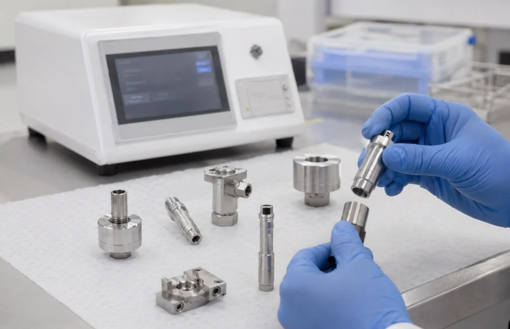
ISO 18250-3 reference connectors are used as defined mating interfaces for enteral reservoir connector testing. In a laboratory test setup, the reference connector provides the required standard interface, while the test sample is evaluated under the specified leakage, stress cracking, mechanical separation, unscrewing or overriding condition.
This page is designed as a selection guide for ISO 18250-3 Annex C reference connectors. It helps customers understand which Figure connector is required for a specific sample type and test purpose.
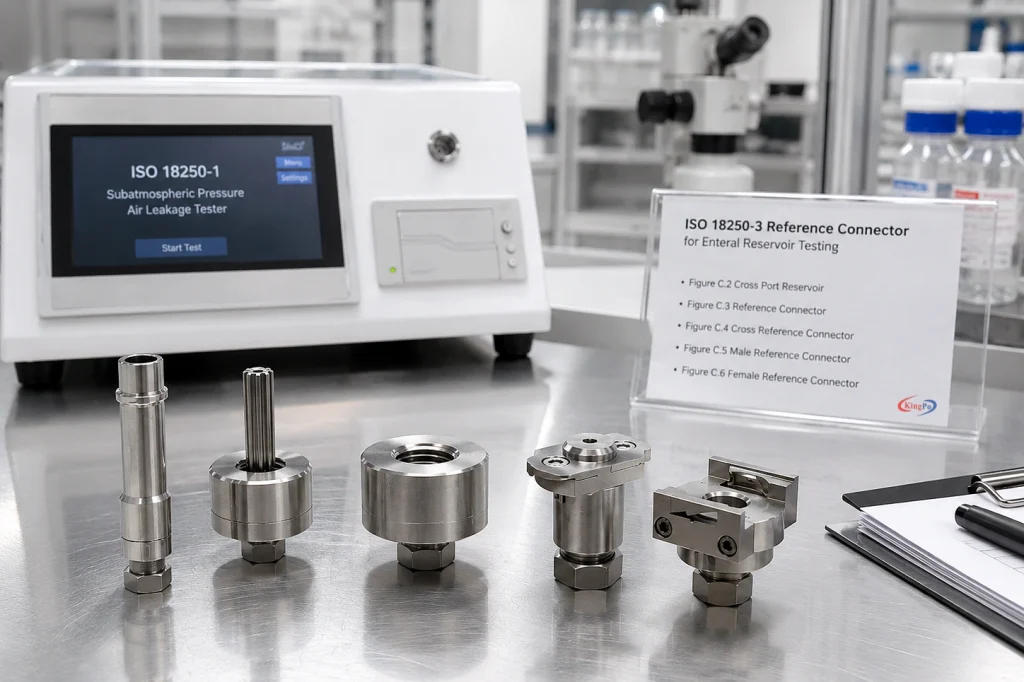
Figure C.1 and Figure C.2 are related to cross connector testing. Figure C.3 and Figure C.4 are used for testing cross port reservoir connectors. Figure C.5 and Figure C.6 are used for female and male enteral reservoir connector testing.
Before ordering, customers should confirm the applicable figure number, sample connector type, test item and documentation requirement. If the required figure is not clear, KINGPO can help review the sample drawing, connector photo or test procedure before recommending the configuration.
ISO 18250-3 Reference Connector Selection Matrix
| ISO 18250-3 Figure | Reference Connector Type | Used to Test | Main Test Purpose | Selection Note |
|---|---|---|---|---|
| Figure C.1 | Cross port reference reservoir connector | Cross connector, E1R | Positive pressure liquid leakage, subatmospheric pressure air leakage, stress cracking, disconnection by unscrewing and separation from unscrewing | Select when the test sample is a cross connector and the test involves leakage, stress cracking or unscrewing-related verification. |
| Figure C.2 | Cross port reservoir reference connector | Cross connector, E1R | Separation from axial load and resistance to overriding | Select when the cross connector test focuses on axial separation or overriding resistance. |
| Figure C.3 | Cross connector | Cross port reservoir connector, E1R | Positive pressure liquid leakage, subatmospheric pressure air leakage, stress cracking, disconnection by unscrewing and separation from unscrewing | Select when the test sample is a cross port reservoir connector and the test involves leakage, stress cracking or unscrewing-related verification. |
| Figure C.4 | Cross connector | Cross port reservoir connector, E1R | Separation from axial load and resistance to overriding | Select when the cross port reservoir connector test focuses on axial separation or overriding resistance. |
| Figure C.5 | Male reference connector | Female enteral reservoir connector, E2R | Positive pressure liquid leakage, subatmospheric pressure air leakage, stress cracking, resistance to separation from axial load and resistance to overriding | Select when the sample is a female enteral reservoir connector and a male reference interface is required. |
| Figure C.6 | Female reference connector | Male enteral reservoir connector, E2R | Positive pressure liquid leakage, subatmospheric pressure air leakage, stress cracking, resistance to separation from axial load and resistance to overriding | Select when the sample is a male enteral reservoir connector and a female reference interface is required. |
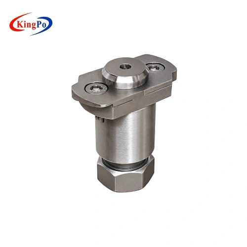
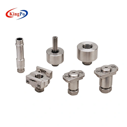
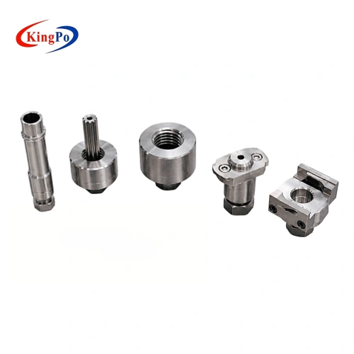
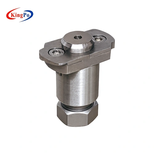
ISO 18250-3 Reference Connector Drawings
Testing Principles for ISO 18250-3 Reference Connectors
ISO 18250-3 connector verification depends on three key conditions: the correct reference connector, controlled assembly and the proper test method. The reference connector provides a repeatable mating interface so the test sample can be evaluated under defined laboratory conditions.
Leakage Test Interface Support
For positive pressure liquid leakage or subatmospheric pressure air leakage tests, the test sample is assembled with the required ISO 18250-3 reference connector. The reference connector provides the mating interface, while leakage test equipment or an external test setup provides the required pressure condition.
The pressure condition, holding time, test medium, fixture interface and acceptance criteria should be confirmed according to the applicable test method. The reference connector is part of the controlled test setup, not a complete leakage tester by itself.
Stress Cracking Test Support
For stress cracking evaluation, the reference connector may be used to maintain the required mating or assembled condition during the test. This helps the laboratory evaluate whether the connector material or interface shows cracking risk under the specified test environment.
The test medium, exposure condition, inspection method and judgment criteria should be confirmed according to the applicable clause or customer procedure.
Axial Separation Test Support
For resistance to separation from axial load, the test sample and reference connector are assembled in the required direction. A controlled axial force is then applied according to the test method.
Fixture alignment is important in this type of test. Side loading, unstable clamping or incorrect orientation may affect the result. The correct Figure connector should be selected according to the test sample and the required axial load test item.
Unscrewing and Overriding Verification
Some ISO 18250-3 test configurations involve disconnection by unscrewing, separation from unscrewing or resistance to overriding. In these tests, the reference connector provides the defined mating interface required for repeatable verification.
The tightening method, rotation direction, axial load direction, fixture alignment and assembly condition should follow the applicable laboratory procedure.
ISO 18250-3 Test Purpose Mapping
| Test Purpose | Related Figure Connectors | What It Helps Verify |
| Positive pressure liquid leakage | C.1, C.3, C.5, C.6 | Whether the connector assembly can maintain liquid tightness under the required positive pressure condition. |
| Subatmospheric pressure air leakage | C.1, C.3, C.5, C.6 | Whether the connector assembly can maintain air tightness under subatmospheric pressure conditions. |
| Stress cracking | C.1, C.3, C.5, C.6 | Whether the connector material or assembled interface shows cracking risk under the required test condition. |
| Disconnection by unscrewing | C.1, C.3 | Whether the connector can be disconnected by unscrewing according to the defined test setup. |
| Separation from unscrewing | C.1, C.3 | Whether the connector separates or resists separation under unscrewing-related conditions. |
| Separation from axial load | C.2, C.4, C.5, C.6 | Whether the connector assembly resists separation under an axial load condition. |
| Resistance to overriding | C.2, C.4, C.5, C.6 | Whether the connector prevents overriding or incorrect engagement under the defined mechanical condition. |
Applications of ISO 18250-3 Reference Connectors by Figure
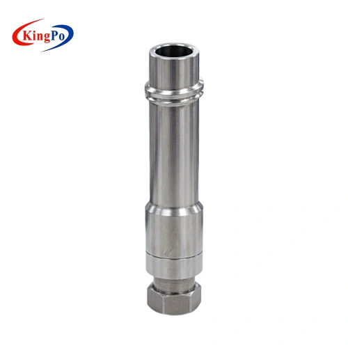
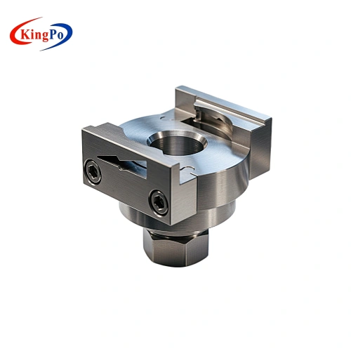
- Figure C.1 Cross Port Reference Reservoir Connector
Figure C.1 is selected when the test sample is a cross connector and the test setup requires a cross port reference reservoir connector interface.
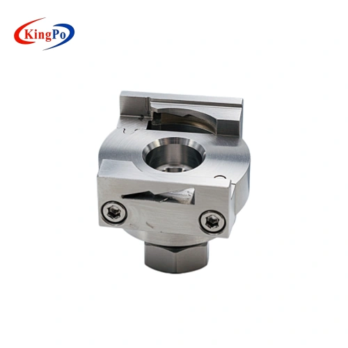
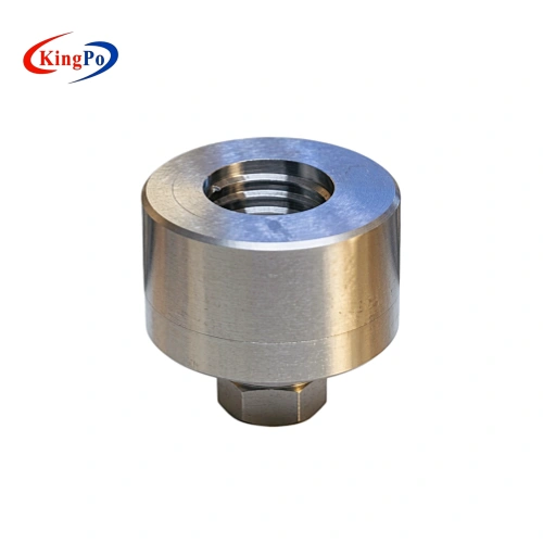
- Figure C.2 Cross Port Reservoir Reference Connector
Figure C.2 is selected when the test sample is a cross connector and the test focuses on axial separation or resistance to overriding.
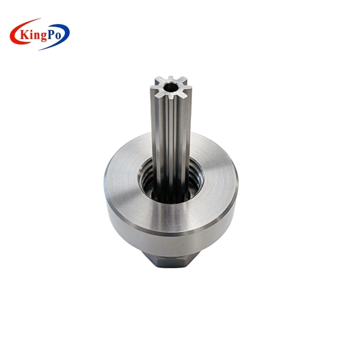
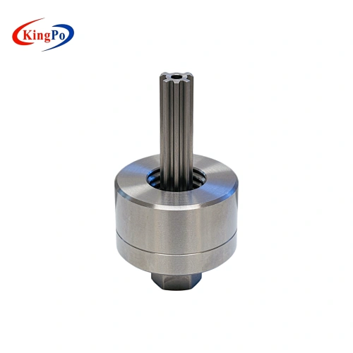
- Figure C.3 Cross Connector
Figure C.3 is selected when the test sample is a cross port reservoir connector and the test setup requires a defined cross connector interface.
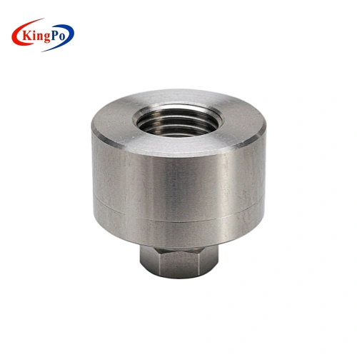
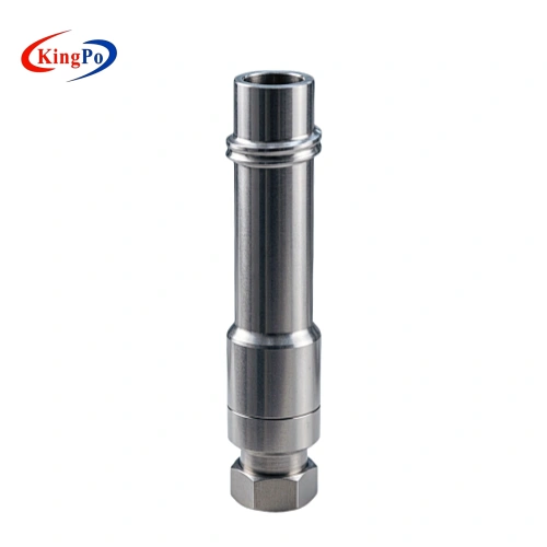
- Figure C.4 Cross Connector
Figure C.4 is also used for testing cross port reservoir connectors, but it is mainly selected for axial separation and resistance to overriding verification.
- Figure C.5 Male Reference Connector
Figure C.5 is a male reference connector used when the device under test is a female enteral reservoir connector. It provides the required male mating interface for E2R-related ISO 18250-3 verification.
- Figure C.6 Female Reference Connector
Figure C.6 is a female reference connector used when the device under test is a male enteral reservoir connector. It provides the required female mating interface for E2R-related ISO 18250-3 verification.
Material, Surface and Dimensional Requirements
ISO 18250-3 reference connectors are precision reference parts. Their function depends not only on overall geometry, but also on material stability, critical surface condition and dimensional control.
Reference connectors should be manufactured from corrosion-resistant rigid materials. Critical surfaces require controlled surface roughness according to Annex C requirements. This is important because surface finish, thread condition and mating surfaces may influence leakage behavior, assembly consistency and mechanical test results.
The drawings for Figure C.1 to Figure C.6 are dimensioned in millimetres unless otherwise indicated. Some dimensions may relate to gasket or mating conditions, so drawing notes and the actual test setup should be reviewed carefully before fixture design or connector selection.
KINGPO can provide ISO 18250-3 reference connectors according to the required figure number and product configuration. If dimensional information or additional project documentation is required, it should be confirmed before order placement.
How to Choose the Correct ISO 18250-3 Reference Connector
Correct selection starts from the test sample and the required test purpose. A male or female reference connector should be selected according to the mating side required by the test method, not only by the connector name.
Step 1: Confirm the Test Sample Type
Identify whether the sample is a cross connector, cross port reservoir connector, female enteral reservoir connector or male enteral reservoir connector.
Step 2: Confirm the Test Purpose
Confirm whether the test is for leakage, stress cracking, axial separation, unscrewing-related verification or resistance to overriding.
Step 3: Confirm the Required Figure Number
Once the sample type and test purpose are clear, the applicable ISO 18250-3 Figure connector can be selected.
Step 4: Confirm the Complete Test Setup
For leakage-related tests, the reference connector may need to be used with leakage test equipment, adapters, tubes, fixtures or sample holders. For mechanical tests, fixture alignment and loading direction should be confirmed.
Step 5: Confirm Documentation Requirement
Customers should confirm whether they need a datasheet, dimensional information, operation manual, calibration-related document or other project documentation before ordering.
Optional Supporting Equipment for Leakage Testing
Some ISO 18250-3 reference connector tests involve positive pressure liquid leakage or subatmospheric pressure air leakage. In these cases, the reference connector may need to be used together with suitable leakage test equipment and fixtures.
KINGPO can provide ISO 18250-1 subatmospheric pressure air leakage test equipment as optional supporting equipment when the selected test method requires air leakage verification. The required pressure condition, fixture interface, adapter, tubing and documentation should be confirmed according to the customer’s test procedure.
The leakage tester should be treated as supporting equipment for the test setup, while the ISO 18250-3 reference connector provides the required mating interface.
-
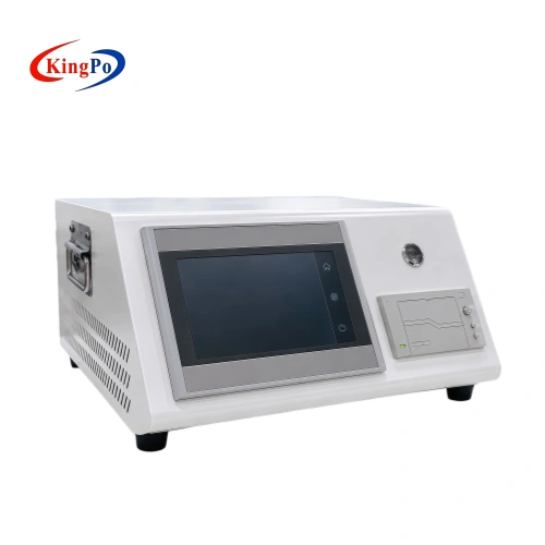
iso-18250-1-air-leakage-tester-front-angle-view