Side detail of ISO 18250-3 Figure C.4 cross reference connector for axial load separation test setup
ISO 18250-3 Figure C.4 cross reference connector for cross-port reservoir connector testing
Angled view of ISO 18250-3 Figure C.4 cross reference connector for reservoir delivery system testing
ISO 18250-3 Figure C.4 cross connector technical drawing for axial load separation and overriding resistance testing

ISO 18250-3 Figure C.4 Cross Reference Connector

The ISO 18250-3 Figure C.4 Cross Reference Connector is a stainless steel reference connector used for cross-port reservoir connector test setups. It is mainly applied in ISO 18250-3 related mechanical performance evaluations, especially where resistance to separation from axial load and resistance to overriding need to be checked.

  • Applicable Standard: ISO 18250-3 Figure C.4
  • Product Type: Cross reference connector
  • Test Sample: Cross-port reservoir connector / reservoir delivery system connector
  • Application: Enteral reservoir connector mechanical performance testing
  • Material: Stainless steel
  • Typical Test Use: Resistance to separation from axial load and resistance to overriding test setups
  • Configuration Note: The required fixture, sample holding method and loading direction should be confirmed according to the selected ISO 18250-3 test item.

Product Overview

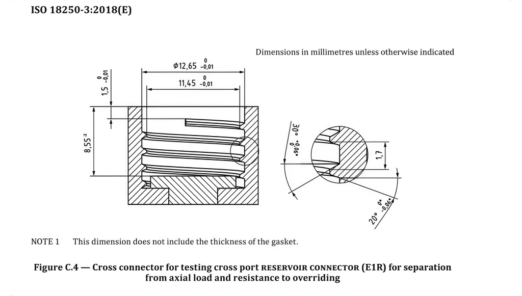
Role of the Figure C.4 Cross Reference Connector in Testing

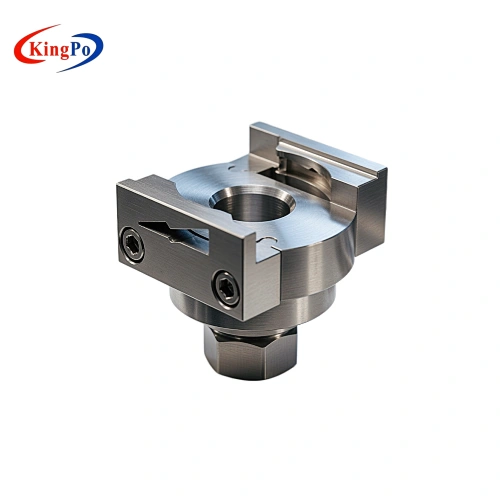
The ISO 18250-3 Figure C.4 Cross Reference Connector is used in test configurations where a cross-port reservoir connector needs to be evaluated under mechanical loading conditions. Unlike C.5 and C.6 reference connectors, which are mainly selected according to male or female mating direction, Figure C.4 is more closely related to cross-port connector structure and mechanical resistance verification.

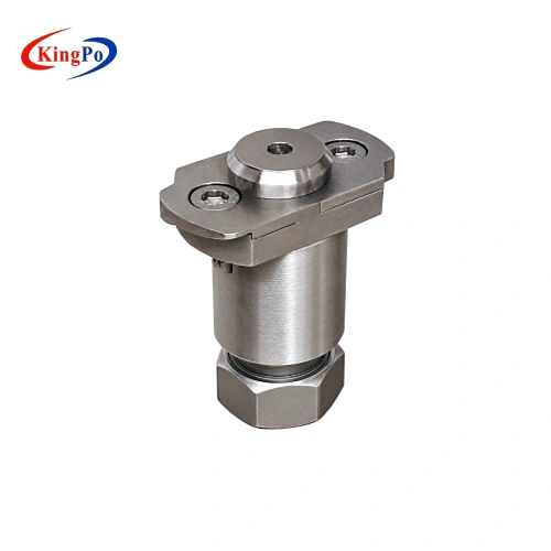
During testing, the reference connector is used with the customer’s sample and the required fixture so that the connector interface can be subjected to the specified loading condition. This helps evaluate whether the cross-port reservoir connector can maintain the required connection performance when exposed to axial load or overriding-related stress.

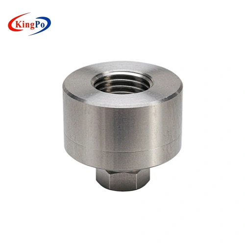
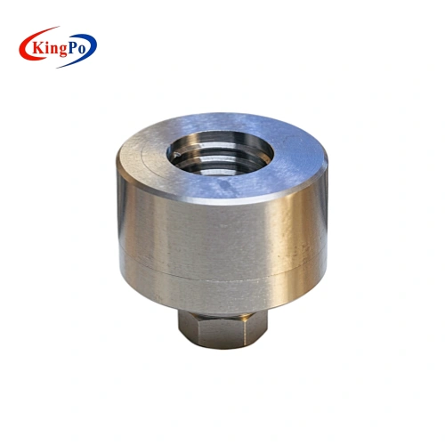
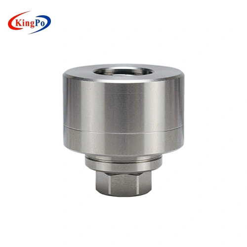
KINGPO supplies the Figure C.4 cross reference connector as a precision-machined stainless steel component for ISO 18250-3 related connector verification. The final test configuration should be confirmed according to the customer’s sample structure, test clause and required loading method.

What This ISO 18250-3 Figure C.4 Connector Is Used For

The Figure C.4 cross reference connector is mainly used for cross-port reservoir connector related mechanical test setups. Its role is to provide a defined reference interface so that the sample connector can be evaluated under controlled test conditions.

Typical applications include:

  • Cross-port reservoir connector verification
  • Reservoir delivery system connector mechanical performance testing
  • Resistance to separation from axial load test setup
  • Resistance to overriding test setup
  • Connector interface stability evaluation
  • Product validation for enteral reservoir connector designs
  • Laboratory quality control and pre-compliance checking

The exact test method, loading condition and fixture arrangement should be confirmed according to the applicable ISO 18250-3 requirement and the customer’s sample design.

ISO 18250-3 Figure C.4 cross connector technical drawing for axial load separation and overriding resistance testing

Mechanical Test Setup Notes

Figure C.4 is normally used as part of a mechanical connector test configuration rather than as a standalone measuring tool. For axial load related testing, the sample connector and reference connector need to be aligned and held properly so that the load is applied in the intended direction.

For overriding resistance evaluation, the fixture design and sample positioning are important because the result may be affected by connector alignment, mating condition and the way force is applied. Customers should confirm whether the project requires only the Figure C.4 reference connector or a complete fixture arrangement for the selected test item.

Before quotation, it is helpful to confirm:

  • Required ISO 18250-3 figure number
  • Sample connector structure
  • Intended test item, such as axial separation or overriding
  • Required loading method or fixture arrangement
  • Whether a single reference connector or a complete test setup is needed
  • Documentation requirements for dimensional inspection or material information

Configuration and Documentation Notes

The Figure C.4 cross reference connector is made from stainless steel and intended for repeated laboratory handling when properly used, cleaned and stored. Since cross-port connector testing may require controlled alignment and mechanical loading, the reference connector should be selected together with the required test method and fixture configuration.

Documentation requirements can be discussed before order. Depending on the project scope, dimensional inspection records, material information or other supporting documents may be prepared according to the agreed supply requirements.

Technical Features

Item Description
Standard Reference ISO 18250-3 Figure C.4
Connector Type Cross reference connector
Typical Test Sample Cross-port reservoir connector / reservoir delivery system connector
Main Application Enteral reservoir connector mechanical performance testing
Material Stainless steel
Typical Test Setup Axial load separation and overriding resistance related configurations
Supply Form Single reference connector or part of an ISO 18250-3 connector configuration
Documentation Dimensional or material documentation can be discussed before order

Technical Inquiry & Expert Support

ISO 18250-3 cross-port connector testing may vary according to the sample structure, loading direction and selected performance requirement. KINGPO supports configuration review for Figure C.4 applications, including reference connector selection, mechanical fixture considerations and documentation requirements.

For projects involving cross-port reservoir connector verification, our team can assist in confirming the suitable ISO 18250-3 connector configuration before quotation.

Typical Users

This reference connector is suitable for:

  • Medical device manufacturers developing reservoir delivery system connectors
  • Enteral reservoir connector and accessory manufacturers
  • Third-party medical device testing laboratories
  • Product validation and quality control departments
  • R&D teams evaluating cross-port connector performance
  • Laboratories requiring ISO 18250-3 related reference connectors and mechanical test fixtures

Related KINGPO ISO 18250 Test Equipment

Related Product When to Use
ISO 18250-3 Figure C.5 Male Reference Connector For test setups requiring a defined male reference connector
ISO 18250-3 Figure C.6 Female Reference Connector For test setups requiring a defined female reference connector
ISO 18250-3 Figure C.3 Reference Connector For ISO 18250-3 connector verification requiring Figure C.3
ISO 18250-3 Figure C.2 Cross Port Reservoir Reference Connector For cross-port reservoir connector related configurations
ISO 18250-1 Subatmospheric Pressure Air Leakage Tester For air leakage testing where the selected ISO 18250 configuration requires leakage equipment
ISO 18250-3 Reference Connectors Selection Guide For complete ISO 18250-3 Figure C.1 to C.6 reference connector selection, test purpose comparison and configuration guidance

ISO 18250-3 Figure C.4 Cross Reference Connector

FAQ

What is the ISO 18250-3 Figure C.4 Cross Reference Connector used for?
It is used in ISO 18250-3 related cross-port reservoir connector test setups. Its main application is mechanical performance evaluation, especially resistance to separation from axial load and resistance to overriding.
Is Figure C.4 the same as Figure C.5 or Figure C.6?
No. Figure C.5 and Figure C.6 are mainly selected according to male or female reference connector direction. Figure C.4 is a cross reference connector used for cross-port reservoir connector related configurations, so the test setup focus is different.
What sample should be confirmed before ordering Figure C.4?
The customer should confirm whether the sample is a cross-port reservoir connector or another reservoir delivery system connector structure requiring Figure C.4. A drawing, photo or standard clause reference can help avoid selecting the wrong connector.
Does this connector complete the full test by itself?
No. The Figure C.4 connector is a reference connector, not a complete test instrument. Axial load separation and overriding tests normally require suitable holding fixtures, loading equipment and sample alignment.
Can Figure C.4 be supplied with a mechanical test fixture?
The reference connector can be discussed together with related fixture requirements. The fixture design depends on the test item, sample structure, loading direction and required test method.
Can KINGPO provide Figure C.4 together with other ISO 18250-3 connectors?
Yes. Figure C.4 can be discussed as a single item or as part of a broader ISO 18250-3 reference connector configuration, depending on the required figure numbers and test items.
What information is needed before quotation?
Please confirm the required figure number, sample connector structure, intended test item and whether only the reference connector or a complete mechanical test setup is needed. Documentation requirements should also be confirmed before order.

Related Products

Related News

The Ultimate Guide to ISO 80369 Luer Gauge Testing ensures your connectors meet safety standards, prevent misconnections, and maintain compliance with reliable testing procedures.

ISO 80369-7 Figure C.2 Male Luer Lock Reference Connector Our 80369-7 compliant Figure C.2 male luer reference connectors are precision-engineered […]

Compare KP8850 and QA-ES III ESU Analyzers for accuracy, workflow, compliance, and usability to choose the right ESU Analyzer for your clinical or lab needs.
A LUER GAUGE checks medical device connectors for secure fit, preventing leaks and ensuring patient safety in clinical settings.
ISO 80369 test equipment checks medical connectors for compliance, preventing misconnections and ensuring patient safety in healthcare environments.

You rely on the 6% taper angle when using iso 80369-7:2021 luer connectors. This special shape helps iso 80369-7 connectors […]

Scroll to Top

Get A Free Quote Now !

Contact Form
If you have any questions, please do not hesitate to contact us.