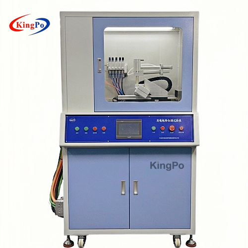
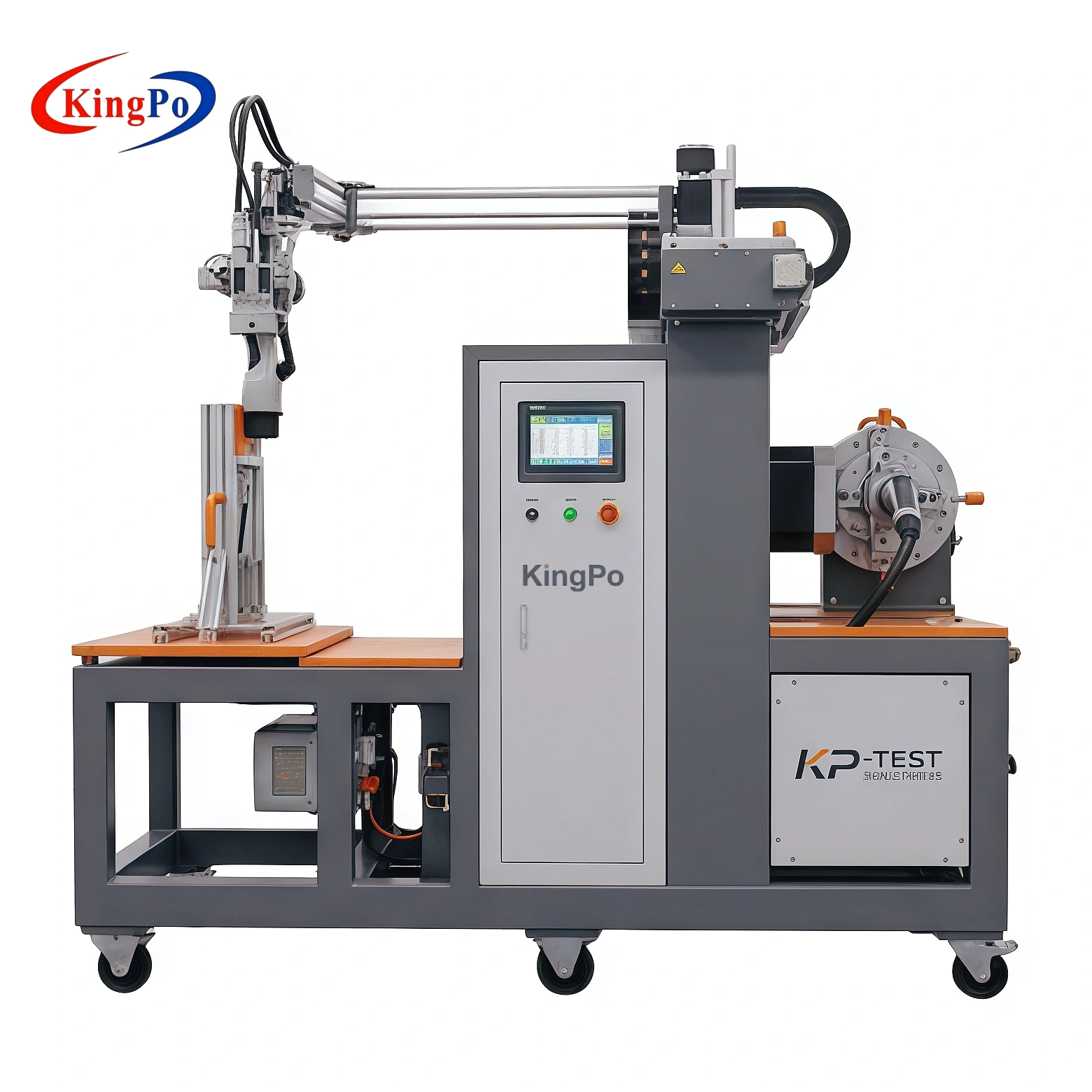
Electronic lock testing evaluates the locking, retaining and release behavior of EV charging connectors and vehicle inlets under repeated mechanical and electrical operation. IEC 62196-1:2025 adds new tests addressing latching devices and retaining means. Laboratory evaluation may therefore consider lock engagement, release force, displacement, status feedback, emergency unlocking and durability according to the applicable connector design and test requirement.
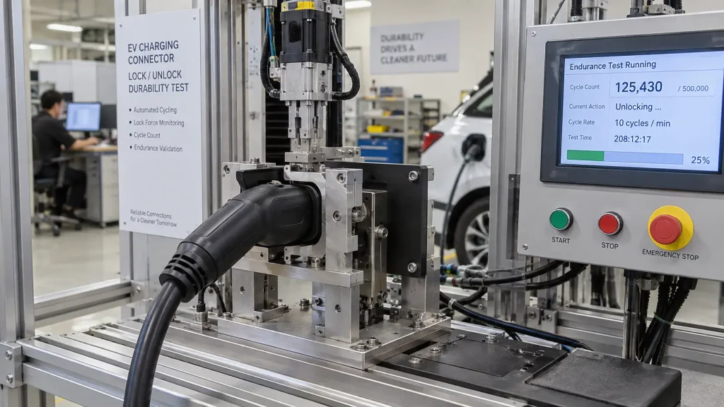
An EV charging connector is more than an electrical interface. In many charging systems, the connector must also remain mechanically secured while charging conditions require it to stay engaged, then release correctly when disconnection is permitted.
This function may involve a mechanical latch, an electrically actuated locking pin, a motor or solenoid, position detection, status-feedback signals and an emergency release mechanism. Because these elements interact, evaluating an electronic lock requires more than checking whether it can simply move between “locked” and “unlocked.”
Engineering principle: electronic lock testing should evaluate the complete locking function—mechanical engagement, release behavior, movement, electrical actuation and status feedback— rather than treating the lock as an isolated switch.
What Is an Electronic Lock in an EV Charging Connector?
An electronic lock is an electrically controlled mechanism used to secure or release an EV charging connector or related coupling mechanism. Depending on the product design, the system may contain a small motor, solenoid, locking pin, locking lever, gear mechanism, position sensor, microswitch or other feedback component.
A typical operating sequence may look like this:
Connector engaged → Lock command → Mechanical lock movement → Lock status confirmed
Charging completed / release permitted → Unlock command → Mechanical release → Connector can be removed
The exact sequence depends on the charging system and connector design. The important point for the laboratory is that the mechanical lock position and the electrical status indication should be evaluated together where applicable.
Latching Device, Retaining Means, Electronic Lock and Interlock
Several terms appear in EV connector documentation and are easily confused. They describe related functions, but they should not automatically be treated as interchangeable.
| Term | Practical Meaning | Typical Function |
|---|---|---|
| Latching device | A mechanical latch or catch used to maintain engagement | Prevents unintended separation through a defined mechanical engagement |
| Retaining means | A broader means of maintaining the required coupled condition | Helps keep the connector or accessory from disengaging unintentionally |
| Electronic locking mechanism | An electrically actuated mechanical locking system | Uses an actuator and control signal to move between locked and unlocked states |
| Interlock | A control relationship between system states | May prevent or permit charging, release or another operation according to confirmed conditions |
In practical systems, these functions may work together. For example, the locking mechanism can physically secure the connector while an interlock signal confirms that the required state has been reached.
Important distinction: a mechanical lock performs a physical action; an interlock is primarily a control relationship. A reliable EV coupling can require both.
What Changed in IEC 62196-1:2025?
IEC 62196-1:2025 is Edition 5 of the general requirements standard for EV plugs, socket-outlets, vehicle connectors, vehicle inlets and related cable assemblies used in conductive charging systems.
The 2025 edition replaces IEC 62196-1:2022 Edition 4. One of the significant technical changes identified by IEC is the addition of new tests for latching devices and retaining means.
Why this matters to laboratories
Locking and retention behavior should no longer be treated as a minor accessory detail when planning EV connector test capability. Laboratories need to identify the applicable latching, retaining and locking functions of the product under test and determine the corresponding test configuration from the current standard edition.
This article deliberately does not assign individual force values, cycle counts or acceptance limits to IEC 62196-1 unless those values are confirmed from the applicable test requirement. Equipment measurement range and standard acceptance criteria are different concepts.
What Should Be Verified in an EV Connector Electronic Lock Test?
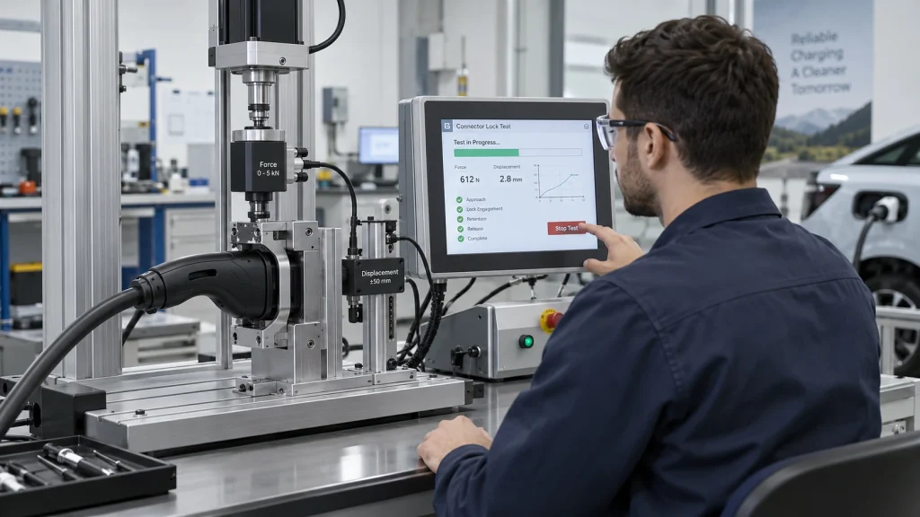
Electronic lock evaluation can involve several mechanical and electrical observations. The exact test items depend on the connector design and applicable requirement.
| Test Item | What It Helps Evaluate |
|---|---|
| Locking operation | Whether the mechanism reaches the intended locked condition |
| Unlocking operation | Whether the mechanism can release correctly when commanded |
| Pull / holding behavior | Mechanical behavior while the connector or locking point is retained |
| Unlocking force | Changes in mechanical resistance during release |
| Displacement | Whether the locking pin, lever or actuator completes the expected movement |
| Operating current | Electrical behavior of the lock actuator or monitored circuit during operation |
| Status feedback | Whether electrical indication corresponds to the actual mechanical lock state |
| Cycle durability | Performance change after repeated lock/unlock operation |
| Emergency unlocking | Whether the mechanism can be released using the intended emergency method where applicable |
KingPo Electronic Lock Tester Measurement Capability
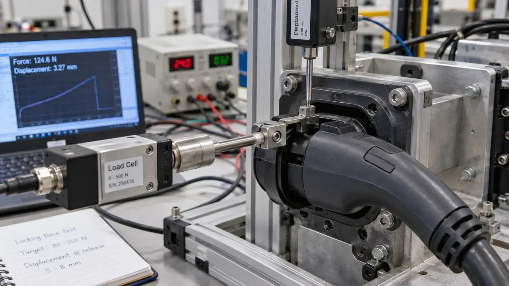
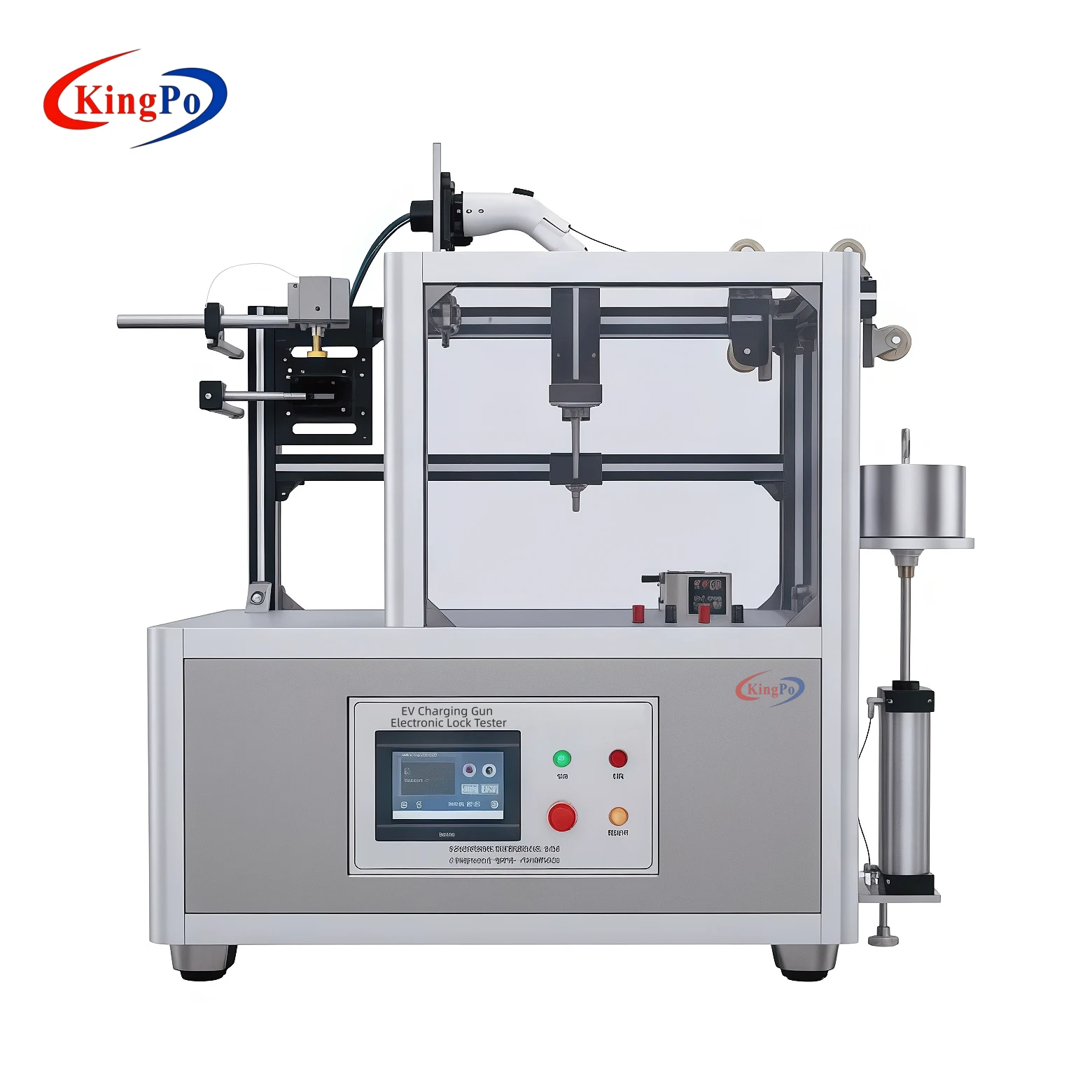
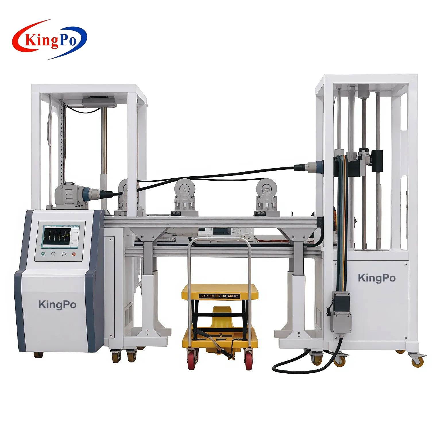
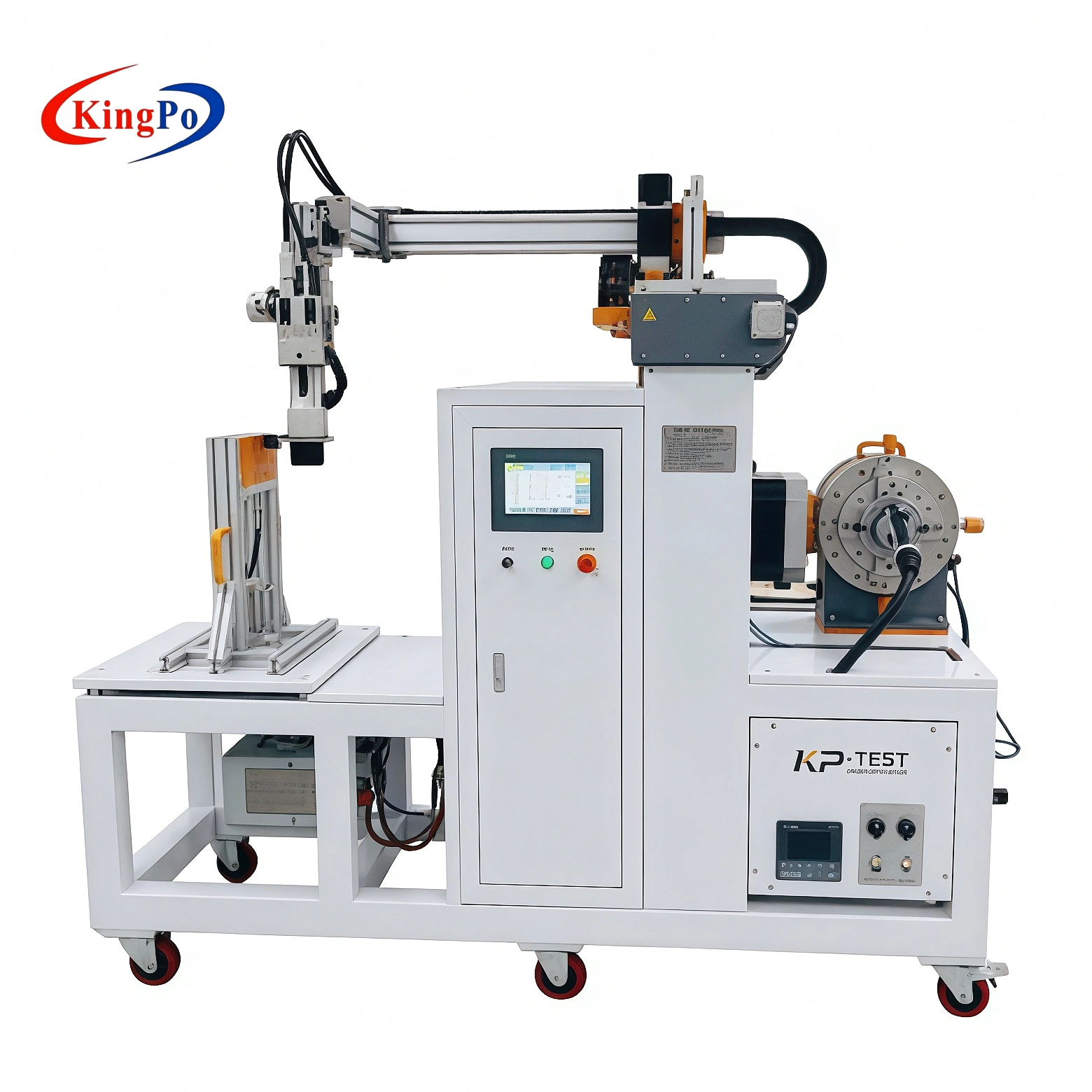
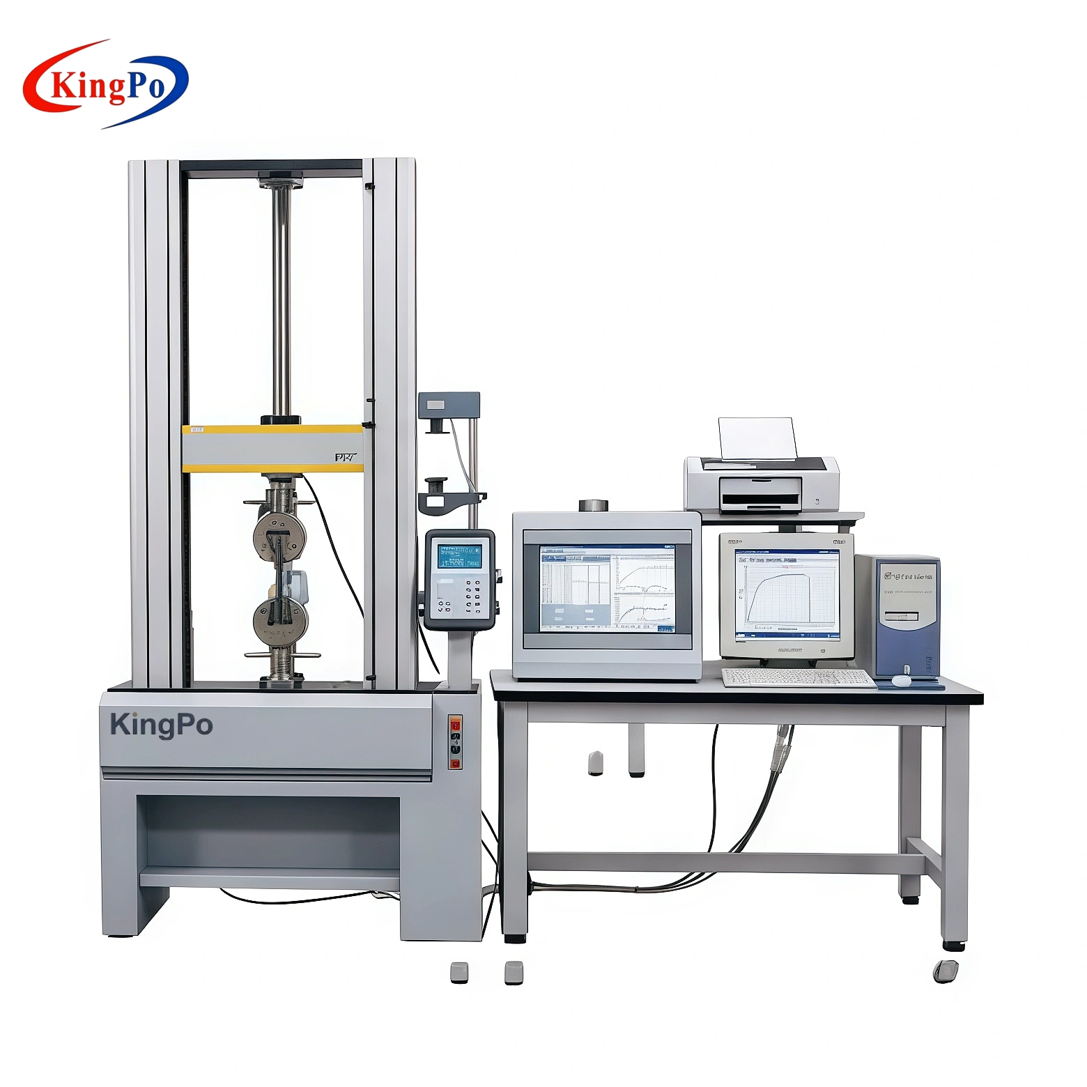
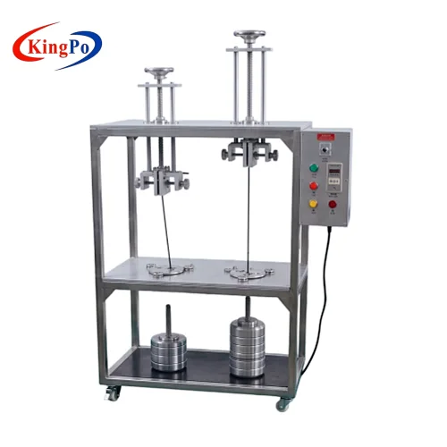
The KingPo EV Charging Gun Electronic Lock Tester combines mechanical force measurement, displacement monitoring, electrical actuation and programmable cycle testing in one laboratory system.
The following values describe the measurement and operating capability of the KingPo tester. They should not be interpreted as universal IEC 62196-1 acceptance limits.
| Parameter | KingPo Tester Capability |
|---|---|
| Pull force | 0–50 N |
| Unlocking force | 0–100 N |
| Force accuracy | ±0.5% F.S. |
| Displacement measurement | 0–50 mm |
| Adjustable load current | 1–200 mA |
| Programmable cycles | Up to 99,999 operations |
| Operation interval | 0–200 s programmable |
| Status monitoring | Real-time lock/unlock signal feedback |
| Emergency release | Manual emergency unlocking test support |
Do not confuse load current with charging current: the 1–200 mA value is associated with the lock test circuit and monitoring function. It is not intended to represent the main high-current charging path of the EV connector.
Typical EV Charging Connector Electronic Lock Test Workflow
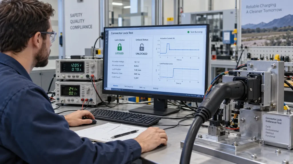
A practical laboratory workflow can be organized as follows. The exact sequence should always be adapted to the connector design, applicable standard and laboratory SOP.
- Identify the locking mechanism. Confirm the locking pin, lever, actuator, feedback connection and emergency-release method.
- Install the connector in the appropriate fixture. Secure the vehicle connector or locking assembly without introducing unintended deformation.
- Align the force application point. The test axis should match the intended locking or release direction to avoid eccentric loading.
- Connect electrical control and feedback signals. Verify polarity, lock command, unlock command and status-feedback connections.
- Set force, displacement and cycle parameters. Use the values required by the applicable test plan rather than assuming that the tester’s full range is required.
- Command the locking operation. Observe actuator movement, displacement, current behavior and lock-status feedback.
- Apply the required mechanical verification. Monitor holding or pull behavior according to the defined procedure.
- Command the unlocking operation. Record release force, movement and feedback response.
- Repeat the programmed cycle sequence. Continue for the specified number of lock/unlock operations.
- Inspect for performance drift or failure. Review abnormal force, incomplete motion, delayed response, sticking or incorrect status feedback.
Common EV Connector Electronic Lock Failure Modes
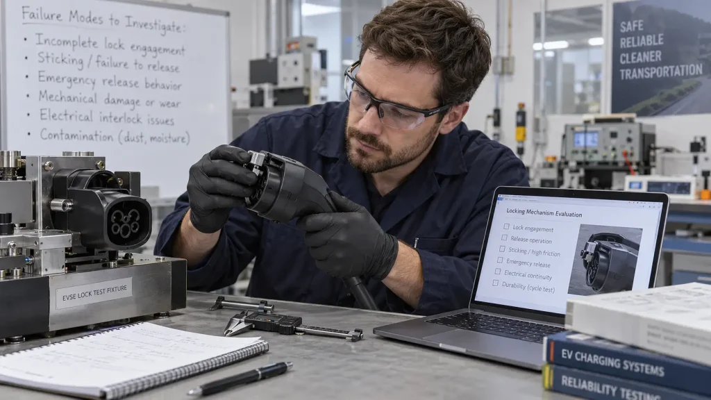
A locking mechanism may perform normally during initial inspection and still degrade after repeated operation. The following failure modes are useful to monitor during development and durability evaluation.
Incomplete Lock Engagement
The locking pin or lever does not reach its intended final position. This can result from insufficient stroke, mechanical obstruction, alignment error or actuator degradation.
Mechanical Sticking
Friction, wear, contamination, deformation or internal misalignment can cause the mechanism to hesitate or remain partially engaged during lock or unlock operation.
Increasing Unlocking Force
A gradual increase in release force can indicate wear, friction growth, dimensional change or increasing resistance within the mechanism.
Displacement Drift
If the actuator or locking member no longer completes the expected travel, mechanical engagement can become incomplete even when the electrical command appears normal.
Incorrect Status Feedback
A serious functional issue occurs when the electrical feedback indicates a locked condition even though the mechanism has not fully engaged, or indicates an unlocked condition while mechanical retention remains.
Delayed Lock or Unlock Response
Longer actuation time can indicate mechanical resistance, actuator deterioration, supply instability or a control-related problem.
Emergency Release Failure
Where an emergency or manual release is part of the product design, it should remain operable under the conditions defined by the applicable evaluation plan.
Fixture-Induced Measurement Error
Not every abnormal result comes from the connector. Poor fixture alignment, eccentric force application or excessive clamping can artificially increase measured force or prevent normal mechanism movement.
Electronic Lock Testing Is Only One Part of IEC 62196-1 Verification
Electronic lock testing focuses specifically on locking, retaining, release and related control behavior. It does not replace the broader IEC 62196-1 evaluation of the complete EV charging connector or cable assembly.
Depending on the product and applicable requirements, broader connector testing may also involve:
- Mechanical insertion and withdrawal
- Operating life and endurance
- Temperature rise
- Contact resistance
- Cable anchorage and mechanical loading
- Electrical safety verification
- Environmental and ingress-protection testing
- Dimensional compatibility
- Other product-specific requirements
For the broader test architecture and reliability considerations, see the IEC 62196-1 EV Charging Connector Testing Guide .
Content boundary
This page focuses on electronic locking, latching and retention behavior. The general IEC 62196-1 guide covers the complete connector test sequence and should be used when planning a broader EV connector laboratory capability.
Electronic Lock Tester vs EV Connector Operating Life Tester
These two systems can appear related because both involve repeated operation, but they evaluate different parts of the connector.
| Test System | Primary Focus |
|---|---|
| Electronic Lock Tester | Lock/unlock operation, force, displacement, actuator behavior, status feedback, emergency unlocking and lock-cycle durability |
| EV Connector Operating Life / Breaking Capacity Tester | Repeated operation of the complete connector, such as insertion, withdrawal and other connector-level endurance conditions according to the applicable test plan |
For connector-level operating life equipment, see the EV Plug Breaking Capacity and Operating Life Tester .
Who Uses EV Charging Connector Electronic Lock Test Equipment?
Electronic lock testing can be relevant to several engineering and laboratory groups:
- EV charging connector manufacturers evaluating lock design and durability
- Vehicle connector suppliers validating actuator, retention and release performance
- Charging equipment manufacturers investigating connector-system behavior
- Certification and test laboratories building IEC 62196-related test capability
- R&D teams comparing locking force, displacement and cycle behavior
- Quality teams reviewing production consistency and failure trends
KingPo also provides broader Vehicle Testing Equipment for EV charging connector, environmental and automotive component test applications.
What Information Should Be Confirmed Before Selecting an Electronic Lock Tester?
“IEC 62196 electronic lock tester” alone may not be enough information to define the correct test configuration. Before equipment selection, the laboratory should confirm:
- Applicable IEC 62196-1 edition and test requirement
- Connector or vehicle inlet type
- Mechanical locking arrangement
- Actuator voltage and control interface
- Lock and unlock signal logic
- Status-feedback circuit
- Required force range
- Required displacement range
- Cycle count and interval requirements
- Emergency or manual release design
- Fixture geometry and force-application point
- Required data recording or reporting functions
Providing these details makes it easier to distinguish between a standard tester configuration and a project requiring a customized fixture or control interface.
Frequently Asked Questions About EV Connector Electronic Lock Testing
What is an electronic lock in an EV charging connector?
It is an electrically controlled mechanical locking mechanism used to secure or release a charging connector or related coupling arrangement. Depending on the design, it may include a motor, solenoid, locking pin, lever, position sensor and electrical status-feedback circuit.
What is the difference between a latching device and an electronic lock?
A latching device generally refers to a mechanical engagement mechanism. An electronic lock uses electrical actuation to control mechanical locking or release. Depending on the product design, an electronic lock may work together with a latch or another retaining mechanism.
What are retaining means in IEC 62196-1?
Retaining means is a broader term for the means used to maintain the intended coupled condition and resist unintended disengagement. The exact implementation and required verification depend on the accessory design and applicable standard requirements.
What does an EV charging electronic lock tester measure?
Depending on the tester configuration, measurements can include locking and unlocking force, displacement, actuator current, lock/unlock status feedback, operation timing and repeated cycle performance. Emergency unlocking can also be evaluated where applicable.
Why is cycle testing important for an electronic locking mechanism?
Locking mechanisms can operate correctly when new but gradually develop increased friction, incomplete movement, actuator degradation, status errors or release problems. Repeated cycle testing helps reveal changes that may not appear during a single functional check.
Does electronic lock testing cover the complete IEC 62196-1 test program?
No. Electronic lock testing addresses locking, retention and release-related behavior. A complete IEC 62196-1 evaluation can also involve electrical, mechanical, thermal, environmental, cable and connector-level tests depending on the accessory and applicable requirements.
Discuss Your EV Connector Electronic Lock Test Requirement
When requesting an electronic lock test system, provide the applicable standard edition, connector type, locking mechanism, control voltage, signal interface, required force and displacement ranges, cycle count and any available test specification or laboratory URS.
KingPo can review the requirement and determine whether the standard EV Charging Gun Electronic Lock Tester configuration or a project-specific fixture is appropriate.